Part 2: Maintenance 5. Replacing the Motors
111
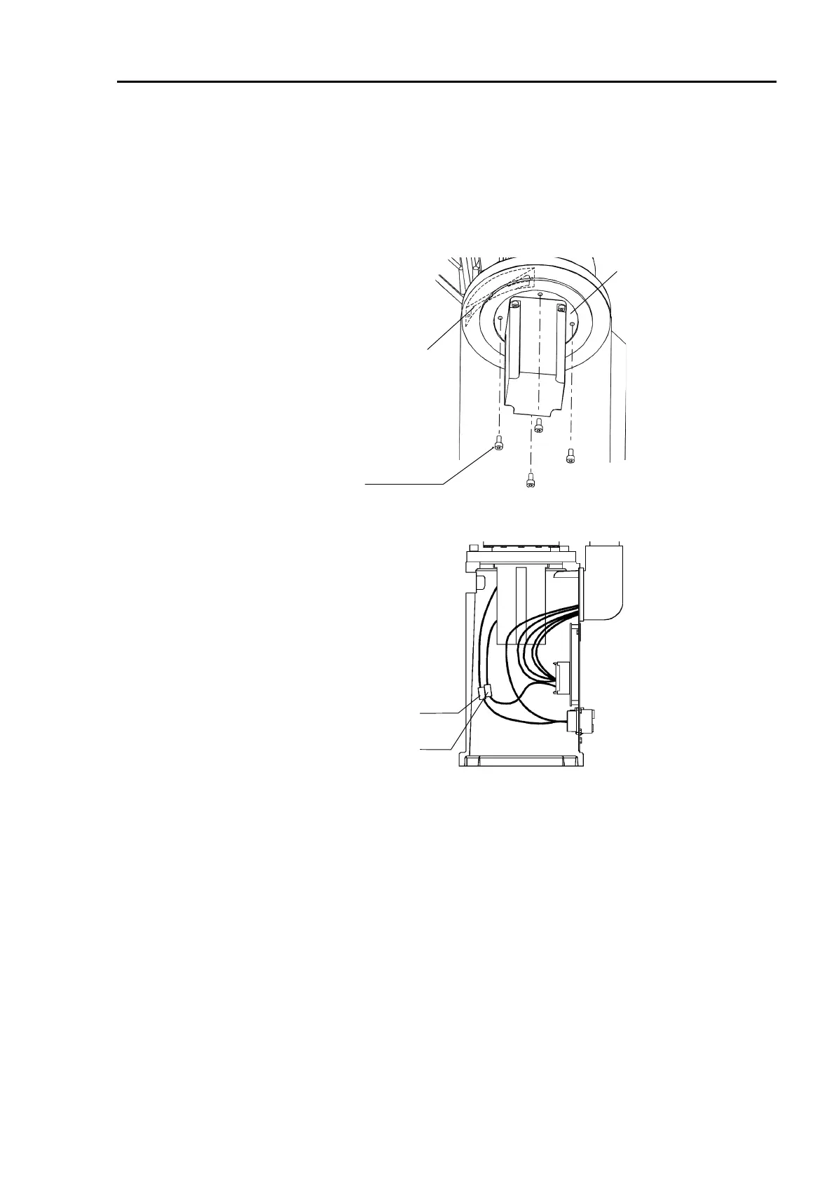
(3) Install the motor flange in the manipulator base with four bolts (M4×15 for the ES
series; M5×15 for the EL series) so that the motor faces the main set by 45 degrees and
the motor cable faces the base connector plate. If the waveform generator does not fit
into the arm easily, move Arm #1 slowly by hand while pushing the wave generator
into place. Insert a hexagon head wrench into the maintenance hole and tighten the
two bolts at the maintenance hole side.
Motor flange
ES: M4× 15
EL: M5× 15
Maintenance hole
(4) Connect the connectors X110 and X11.
X11
X110
(5) Attach the maintenance plate with two bolts (M4×8).
∗ If the manipulator is a Protected model, the maintenance plate must be sealed and
the waterproof cover 1 must be installed. Refer to the section Sealing the
Manipulator in chapter 13. Protected Model Maintenance.
(6) Install the base connector plate. (Refer to chapter 2. Opening the Covers.)
∗ If the manipulator is a Protected model, seal the base connector plate. Refer to the
section Sealing the Manipulator in chapter 13. Protected Model Maintenance.
(7) The mechanical origin position and teach points change when the motor is replaced.
Be sure to calibrate Joint #1. (Refer to chapter 11. Calibration.)
 Loading...


