Part 2: Maintenance 6. Replacing the Reduction Gear Units
149
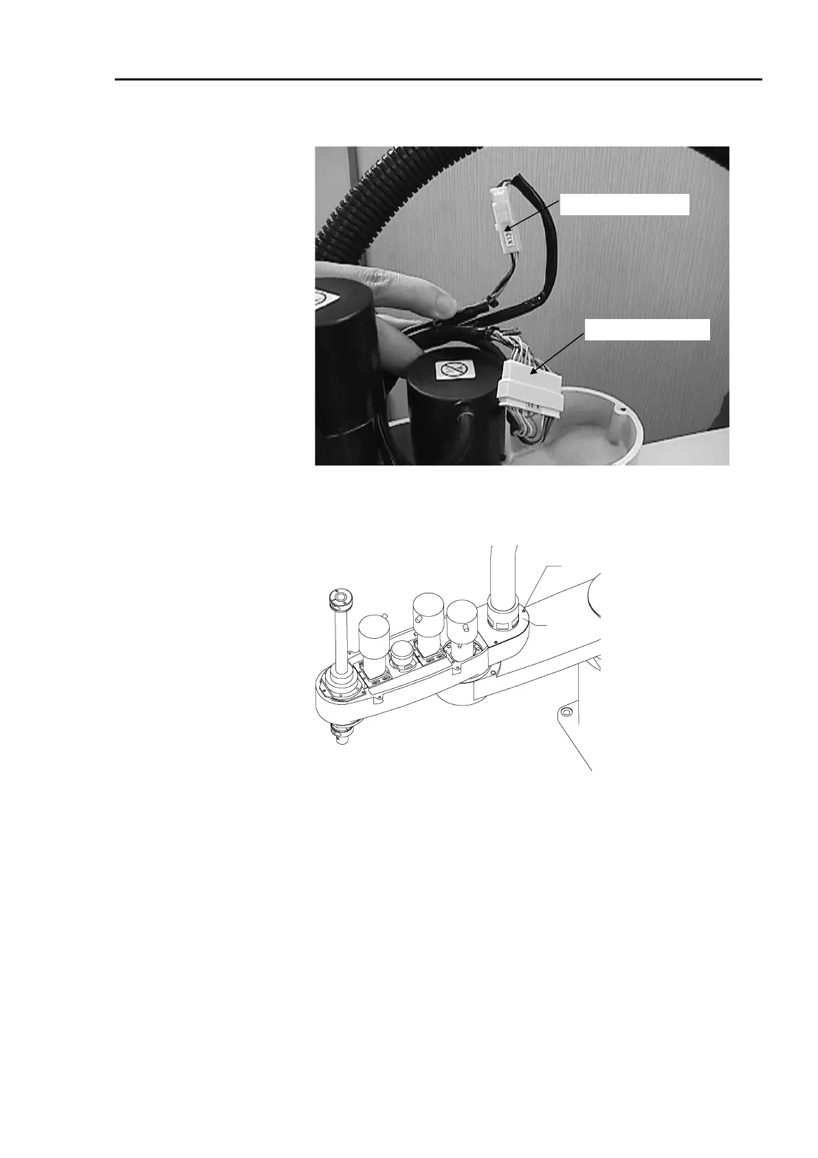
(12) Connect the connectors, X121 and X21 of the Joint #2 motor.
Signal connector X21
Power connector X121
(13) Fasten the motor cables with wire ties in their original positions. Do not allow
unnecessary strain on the cables.
(14) Place the duct plate back on and secure it with three bolts (M4×8).
M4×8
Duct plate
(15) Attach the arm top cover. (Refer to chapter 2. Opening the Covers).
(16) The mechanical origin position and teach points change when the reduction gear unit is
replaced. Be sure to calibrate the Joint #2. (Refer to chapter 11. Calibration.)
 Loading...


