9. Replacing the Ball Screw Spline Unit Part 2: Maintenance
172
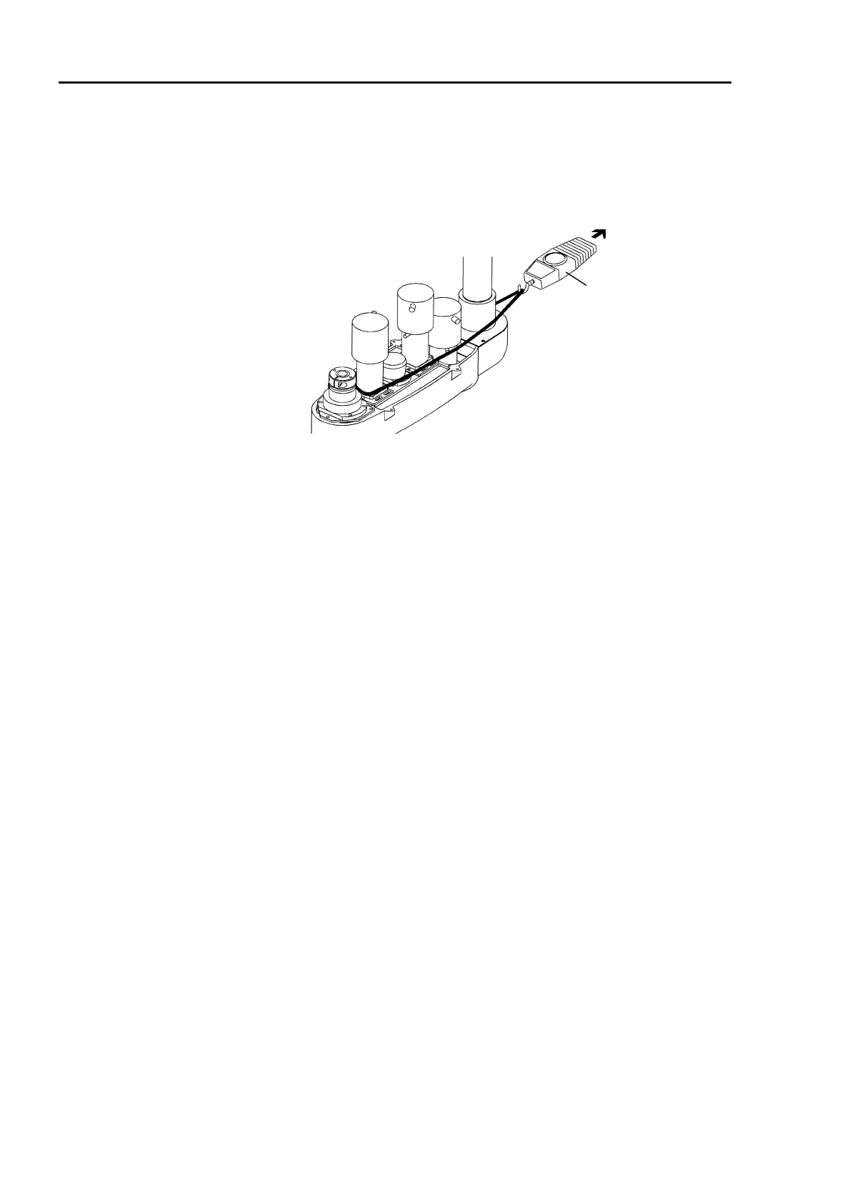
(10) Pass a suitable cord or string around the Joint #3 motor near its mounting plate.
Loosen the bolts for the Joint #3 motor plate fastened in the step (7) and pull the cord
using a force gauge or similar tool. Fasten the Joint #3 motor plate securely where the
Z belt is pulled at 29.4N (3kgf). Adjust in the range of 20N - 39N (2kgf - 4kgf).
Force gauge
(11) Connect the connectors, X131, X31 and X32. Fasten the motor cables with wire ties
in their original positions. Do not allow unnecessary strain on the cables.
(12) If the motion range of Joint #3 was limited by the lower-limit mechanical stop, change
the position of lower-limit mechanical stop to the previous position. Refer to chapter
8. Motion Range and Robot Coordinates in Part 1.
(13) Install the arm top cover and arm bottom arm cover. (Refer to chapter 2. Opening the
Covers.)
∗ If the manipulator is a Protected model, reseal the covers. For detail on sealing the
covers, refer to Sealing the Manipulator in chapter 13. Protected Model
Maintenance.
(14) Grease the shaft (refer to Greasing the Ball Screw Spline Unit on the next page).
∗ If the manipulator is a Clean model, attach the bellows to the manipulator. Refer to
the section Replacing the Bellows in chapter 12. Clean Model Maintenance.
∗ If the manipulator is a Protected model, attach the bellows to the manipulator. Refer
to the section Replacing the Bellows in chapter 13. Protected Model Maintenance.
(15) Install the end effector.
(16) The mechanical origin position and teach points change when the timing belts are
replaced. Calibrate Joint #3 and Joint #4. Refer to chapter 11. Calibration.
 Loading...


