10. Replacing the Signal Relay Board Part 2: Maintenance
176
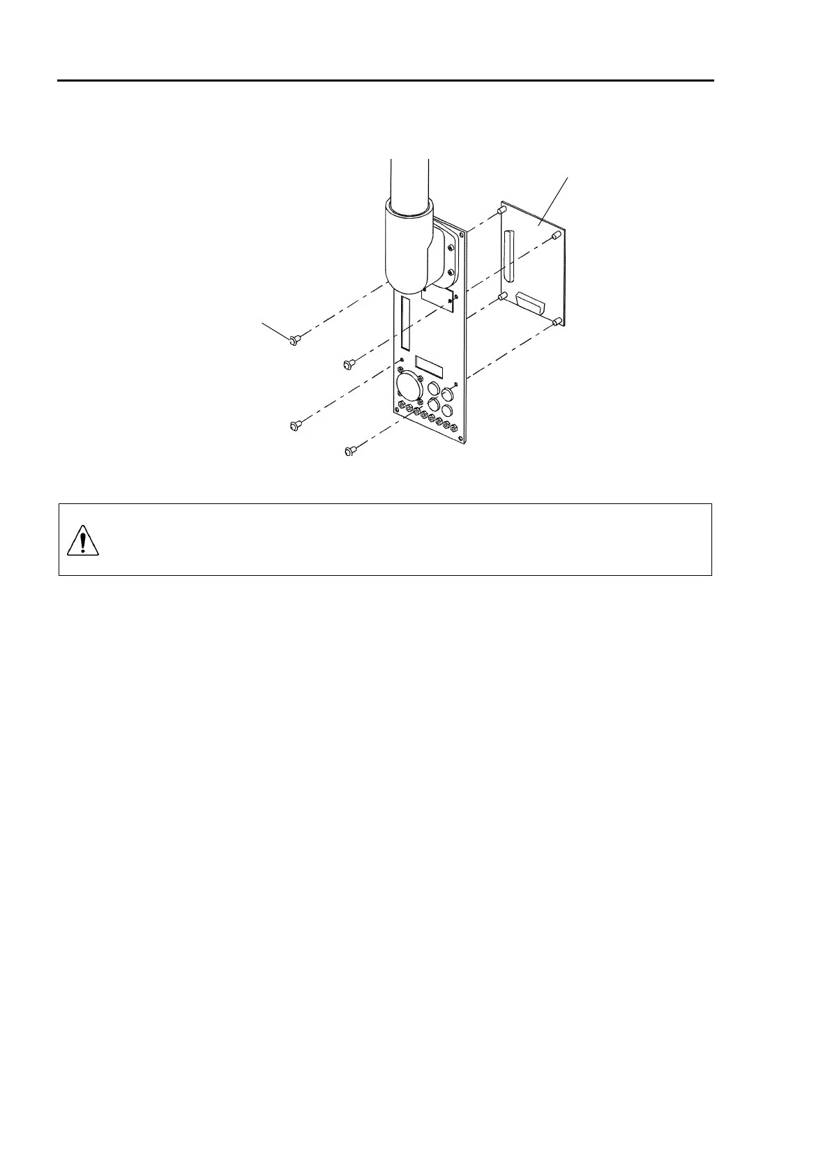
Installation
(1) Install a new signal relay board onto the base connector plate with four M3×6 screws.
M3
×
6
Signal relay board
(2) Securely connect the connectors, X10, X20, X30, X40, and X50.
CAUTION
Be sure to connect the signal connectors securely. Do not bend the cables
sharply or damage them in any way. Abnormal signals may cause the
malfunction of the robot.
(3) Mount the base connector plate on the back of the manipulator. (Refer to chapter 2.
Opening the Covers.)
(4) Connect the cables to the base connector plate.
(5) Turn ON the Controller power and test it with a few teach points to make sure that the
teach positions have not been offset. When you have confirmed that the position data
has been retained, replacement is completed. If there is any position found to be
offset, calibrate the manipulator by referring to chapter 11. Calibration.
 Loading...


