13. Protected Model Maintenance Part 2: Maintenance
208
Removal
(1) Turn OFF the Drive Unit power.
(1) Turn OFF the Controller power.
(2) Disconnect all the connectors and tubes from the base connector plate.
(3) Remove the six bolts (4-M4×8 and 2-M4×16) from the base connector plate and open
the cover forward. Be careful not to pull the base connector plate forcibly since the
strain on the cables may cause wire disconnection and/or damage to silicon rubber
sheet. Also, remember the approximate cable arrangement so that the cables can be
reconnected similarly during replacement.
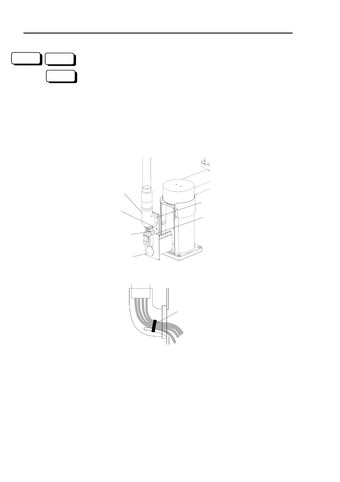
(4) Remove the four mounting bolts (M6×12) from the main cable elbow fitting.
(3) 4-M4×8
Main cable
elbow fitting
(4) M6×12
(6) M3×8
Receptacle
(3) 2-M4×16
(5) Cut off the wire tie inside the main cable elbow fitting.
Wire tie
(6) Remove the four bolts (M3×8) from the receptacle and receptacle itself. If the
receptacle does not come out easily because of the liquid gasket on the junction surface,
use a flat screwdriver between the receptacle and the base connector plate.
(7) Disconnect the ground wires and pneumatic tubes from the base connector plate.
Each pneumatic tube can be pulled out by first pushing the fitting release ring. The
ground wire terminals are fastened with bolts (M4×8).
(8) Open the arm top cover. (Refer to the chapter 2. Opening the Covers.) Be careful
not to pull the arm top cover forcibly since the strain on the connected cables may
cause wire disconnection. Also, pay attention to and remember the approximate cable
arrangement so that the cables can be reconnected similarly during replacement.
300
RC+
SPEL 95
 Loading...


