System 5 Digital Audio Mixing System Operation Manual Dynamic Automation
180
14.2.1 Automation LEDs
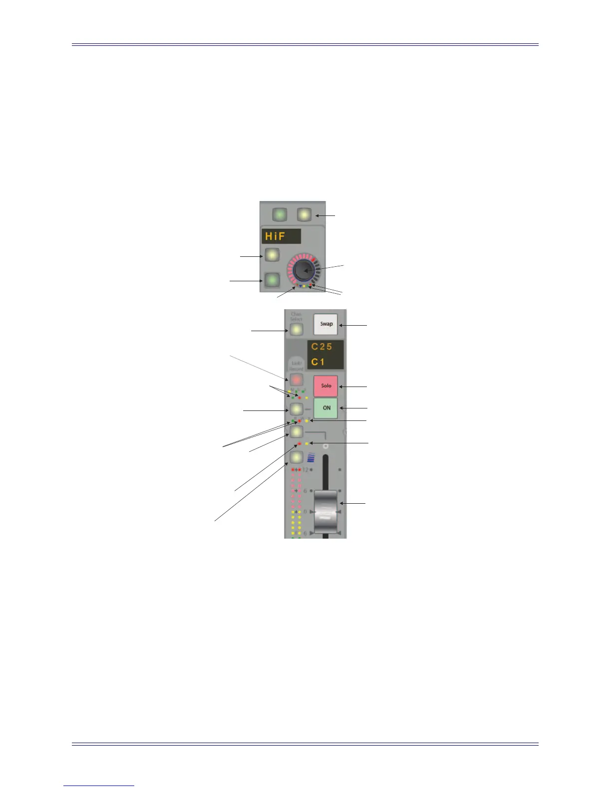
Figure 14-2 shows the fader, switch, and knob automation interfaces. Each automated
parameter has two status LEDs:
• The red LED (right) indicates the parameter is in Write mode.
• The green LED (left) indicates the parameter is in Read mode.
Figure 14-2 Knob (top) and fader (bottom) automation and control features
14.2.2 Select/Punch Keys
Select/Punch keys perform two functions:
• Punch the control into and out of recording automation.
• Assign the selected automation mode to its corresponding parameter.
Chan
Select
Fader Automation
Status LEDs
Fader Select/Punch key
Select/Punch key
Channel On
Channel On
Automation status LEDs
Strip Lock LED
Wave key
All Funcs key
Select/Punch
for On/Off
switch
Knob Select/Punch
switch
Knob Automation
status LEDs
Switch Automation
status LED
On/Off
switch
Knobset
Select/Punch switch
Top of Strip
Channel Select
key
Swap channel
key
Solo
key
Channel On key
Auto-glide LED
Fader touch-
sensor LED
Touch-sensitive
fader