System 5 Digital Audio Mixing System Operation Manual Channels and Strips
105
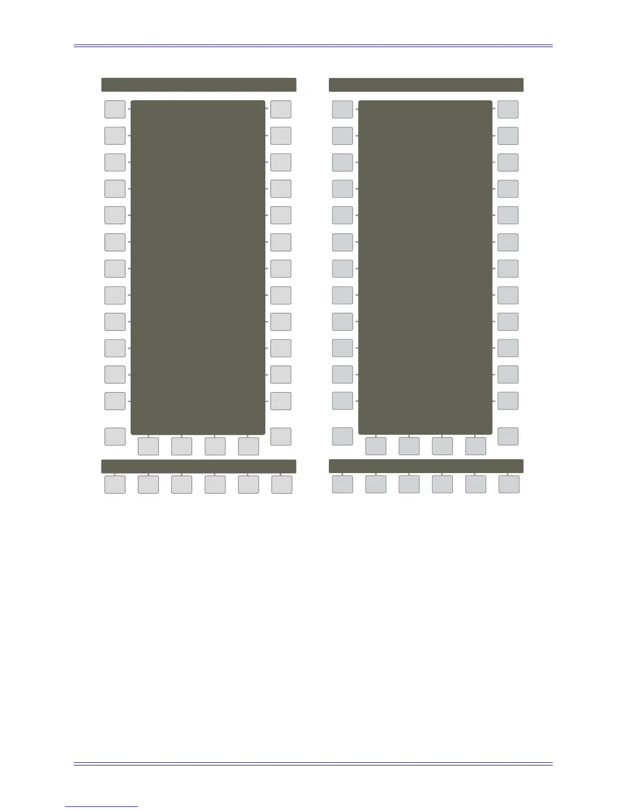
Figure 8-7 Strip Config panel, pages 3 and 4 of 4
Main
Panel
Info
Joystick Assign Mode
Strip Config Page 3
Cycle
402 Cycle
Delay Display Mode:
Samples
Seconds/Frames
Seconds/Millisecs
Pg 3
Main
Panel
Pg 4
Info
Aux View Enabled
Knob Touch Enabled
Strip Config Page 4
Direct Assign
► ◄◄
Joystick Assign Mode
There are three options in the Strips Config Panel (page 3) to select how to
assign the CM403’s joysticks.
Cycle: Allows assigning a channel, control group, or bus to a joystick by
pressing the Wave key of a previously assigned channel strip. For example,
if G1 (Control Group 1) is assigned to a channel strip, pressing its Wave key
will assign G1 to the left joystick. Pressing a Wave key on another assigned
channel strip will assign its channel, control group, or bus to the right joystick.
Left/right joystick assignments alternate with each Wave key press.