System 5 Digital Audio Mixing System Operation Manual Busses and Bus Masters
90
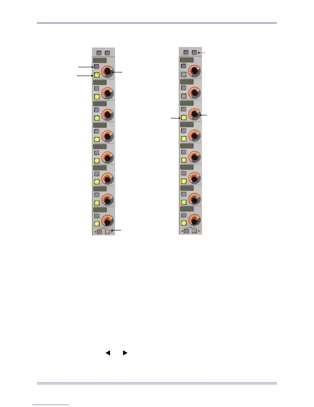
Figure 7-2 Mix Bus Master (left) and Individual Bus (right) Displays
The left side of Figure 7-2 shows the Mix Bus Master display after pressing the Mix
Mstrs button (or the top-right knobset function key next to Clear). The important func-
tions are summarized below:
• Press the upper of the two buttons to the left of each knob to display the indi-
vidual busses for that Mix Section.
• Adjust the knob to control the overall level of that Mix Bus.
• Press a knob to display individual Section meters on the TFT screen.
• Press the lower of the two buttons to the left of each knob to turn that Mix Bus
On/Off. All individual bus parameters are retained if the Bus is turned on after
being off.
• Use the
and buttons to display additional pages if there are more than
eight busses.
Clear
Clear
H
G
F
E
D
C
B
A
Bm51
Sr48
Sl48
R 51
C 51
L 51
Selects individual
sections from this
Main Bus
Turns Main
Bus on/off
Adjusts
level
Mix Bus
section
Page Key
displays additional
Main bus Sections
(if more than 8)
Press this button
or the
button to return
to Main Masters page
Main Mstrs
Turns bus
on/of
f
Adjusts the
bus level