21 Outputs FLUXUS G60x
UMFLUXUS_G6V4-2EN, 2011-03-29 157
21.6.1 Alarm Properties
The switching condition, the holding behavior and the switching function of an alarm out-
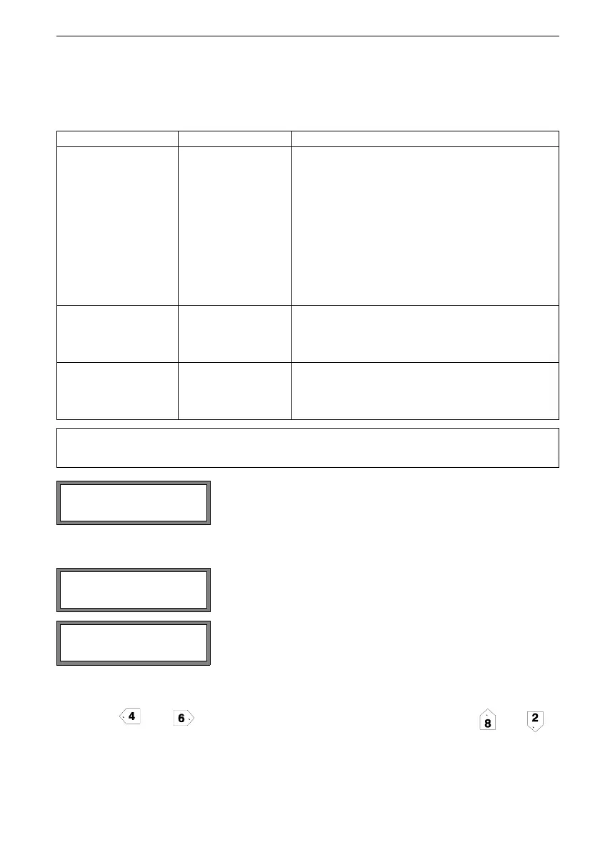
put can be defined.
Press key and to select a scroll list in the upper line. Press key and to
select a list item in the lower line.
Press ENTER to store the settings.
Tab. 21.4: Alarm properties
alarm property setting description
func
(switching condition)
MAX The alarm will switch if the measured value exceeds
the upper limit.
MIN The alarm will switch if the measured value falls be-
low the lower limit.
+
→- -→+ The alarm will switch if the flow direction changes
(sign change of measured value).
QUANT. The alarm will switch if totalizing is activated and the
totalizer reaches the limit.
ERROR The alarm will switch if a measurement is not possi-
ble.
OFF The alarm is switched off.
typ
(holding behavior)
NON-HOLD If the switching condition is not true anymore, the
alarm will return to the idle state after approx. 1 s.
HOLD The alarm remains activated even if the switching
condition is not true anymore.
mode
(switching function)
NO Cont. The alarm is energized if the switching condition is
true and de-energized if idle.
NC Cont. The alarm is de-energized if the switching condition
is true and energized if idle.
Note! If no measurement is made, all alarms will be de-energized, inde-
pendently of the programmed switching function.
Select in the program branch Output Options the chan-
nel for which an alarm output is to be activated. Press EN-
TER.
This display will not be indicated if the transmitter has only
one measuring channel.
Select yes to activate the alarm output. Press ENTER.
Three scroll lists will be displayed:
• func: switching condition
• typ: holding behavior
• mode: switching function
Output Options ↕
for Channel A:
R1=FUNC<typ mode
Function: MAX