Section 4
4-22 © Copyright 2009 GBC. All rights reserved. Advanced Punch Service Manual
a. Unhook the spring of the GP2 aligner latch on the right end.
b. Remove only one (the one closest to the frame) of the E-rings of the GP2
aligner latch on the left end (front Door side).
c. Push the GP2 aligner latch in toward the front door until it clears the rear
frame.
d. Pull the entire GP2 aligner latch, door latch out and set it aside.
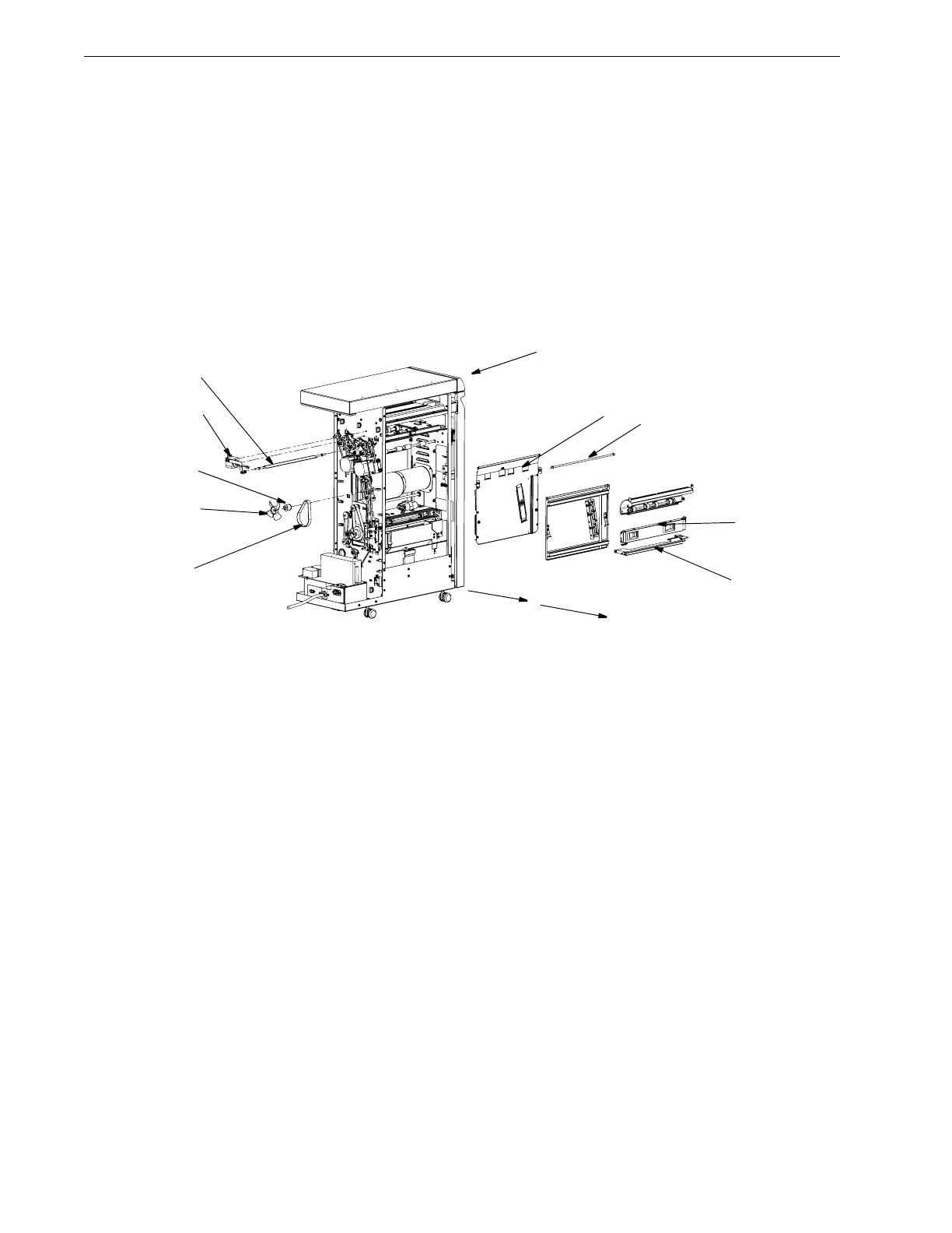
4. To remove Entrance Aligner panel, Idler Paper Guide assembly (refer 4-19):
Figure 4.22Remove Idler Paper Guide Assembly.
a. Remove 2 E-rings from the Pivot shaft [3].
b. Slide the shaft [3] all the way out through the front of the Advanced Punch.
c. Remove the fan [4] that prevents access to the flexible cable. To remove it
simply pull it off of the shaft.
d. Remove the flexible cable using a hex wrench.
e. Remove the rear top motor pulley [5].
f. Loosen the belt [6].
g. Remove the belt and pulley.
h. Loosen screw from the solenoid link.
i. Remove the solenoid assembly [7] and link from the Diverter Shaft, leave it
hang.
j. Remove the 2 E-Rings of the Entrance Diverter assembly, slide the Diverter
out and set it aside [10].
5. To remove the drive side, Paper Entrance Guide Aligner assembly [8], which is
the large sheet metal assembly that actually contains the green drive belt and
[5]
[7]
[9]
[10]
[4]
[6]
[11]