Section 4
4-60 © Copyright 2009 GBC. All rights reserved. Advanced Punch Service Manual
4.9.4 Punch Module Brake Replacement and Adjustment
Procedure
Remove the Punch Module Assembly first, using procedure “Punch Module
Removal” on page 4-49.
To replace the brake, first remove the clutch and related drives. See “Clutch
Replacement” on page 4-55. The brake must be adjusted while on drive shaft. To
adjust the brake, see “Punch Module Brake Adjustment” on page 4-62.
Tools Needed
• Feeler gage, 0.010" (0.25 mm)
• Hex wrenches, 0.05" and 3/32"
• Flat blade screwdriver
• Pliers
4.9.4.1 Punch Module Brake Replacement
To replace the brake:
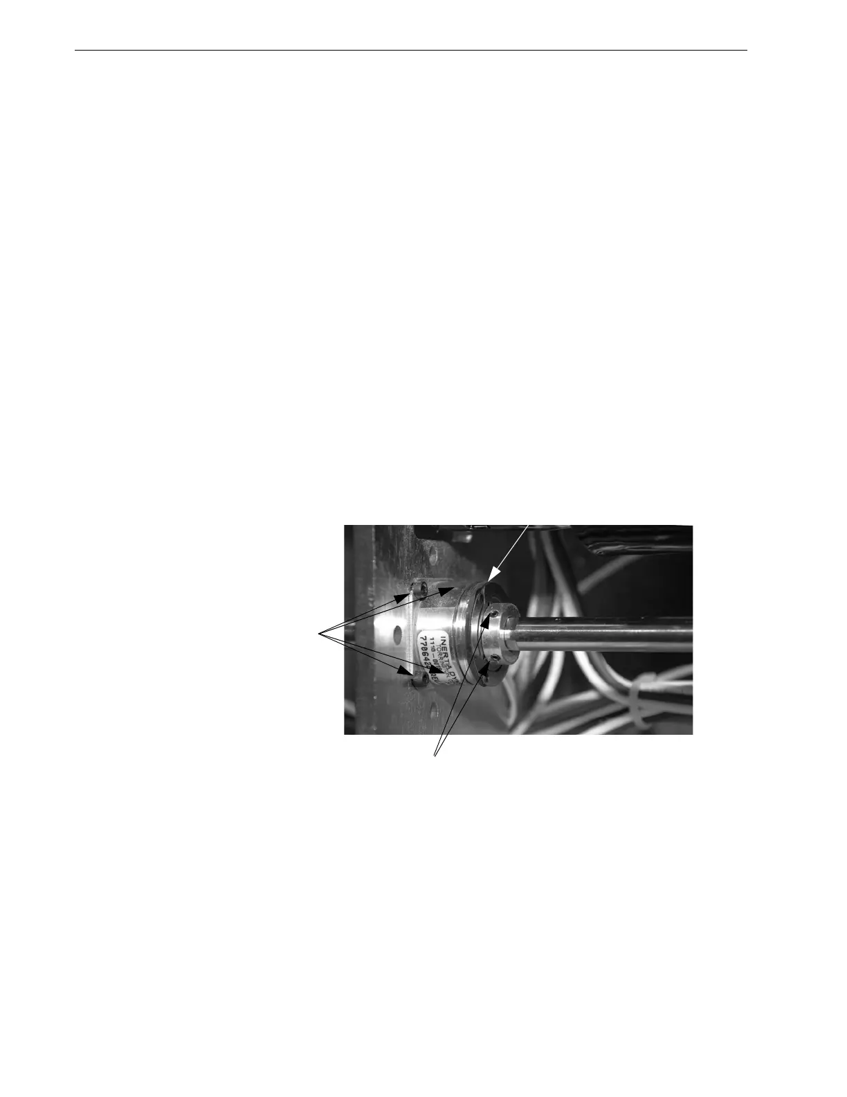
1. Remove the 4 socket head set screws [1].
2. Loosen the 2 set screws [2] until the brake pad [3] slides freely on the shaft.
Figure 4.68 Brake Assembly and Drive Shaft.
Installation Note: When installing the brake, ensure that the 2 set screws
engage the flats on the shaft. To adjust the brake, see “Punch Module Brake
Adjustment” on page 4-62.