Repair and Adjustment Procedures
Advanced Punch Service Manual © Copyright 2009 GBC. All rights reserved. 4-23
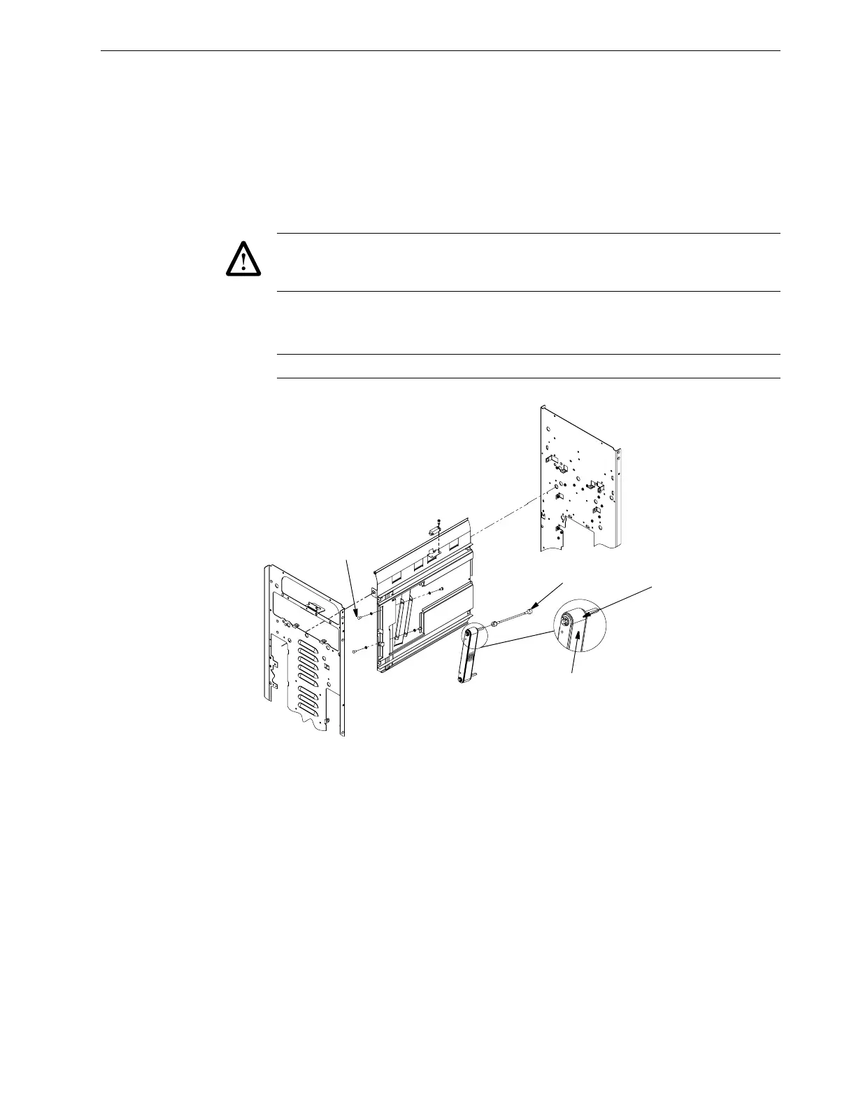
Aligner.
a. Remove the 6 Screws that secure the face of this assembly.
b. Remove the 2 screws that secure this assembly from the side frame.
c. Pull and walk the entire sheet metal assembly of the Paper Guide Aligner
assembly up and outward. You can grab the assembly at the roller cut out
with your fingers.
Caution: As you pull the assembly out, disconnect the sensor harness behind the
assembly as soon as you are able to reach it. Failure to observe this notice may damage the
wiring.
6. Remove the green drive belt Aligner Roller assembly by removing the 4 screws
(S).
Caution: Leave the Flex Shaft (FS) attached.
Figure 4.23Removing the green drive belt.
4.6.3.2 Green Drive Belt Assembly
1. Stretch the new Belt (B) onto the Aligner Roller assembly, green side out.
Rotate the Shaft (S) to confirm that the belt tracks properly.
2. Slide the Aligner into place, loosely attach the"4 Pan Head Screws with the 4
Lock Washers.
a. Check that the metal surface of the Aligner Roller assembly is flush with the
Sheet Metal surface of the Paper Guide. A 12" metal ruler works well to
check this adjustment. Slip the ruler under the green drive belt and press it
flat against the two surfaces.
b. Adjust the Aligner and snug the screws when perfectly flush.