Display Unit for F-CM(C)1 (Rev. 05), F-CM(C)REC1 (Rev. 01)
17
Document no. M1144956-003
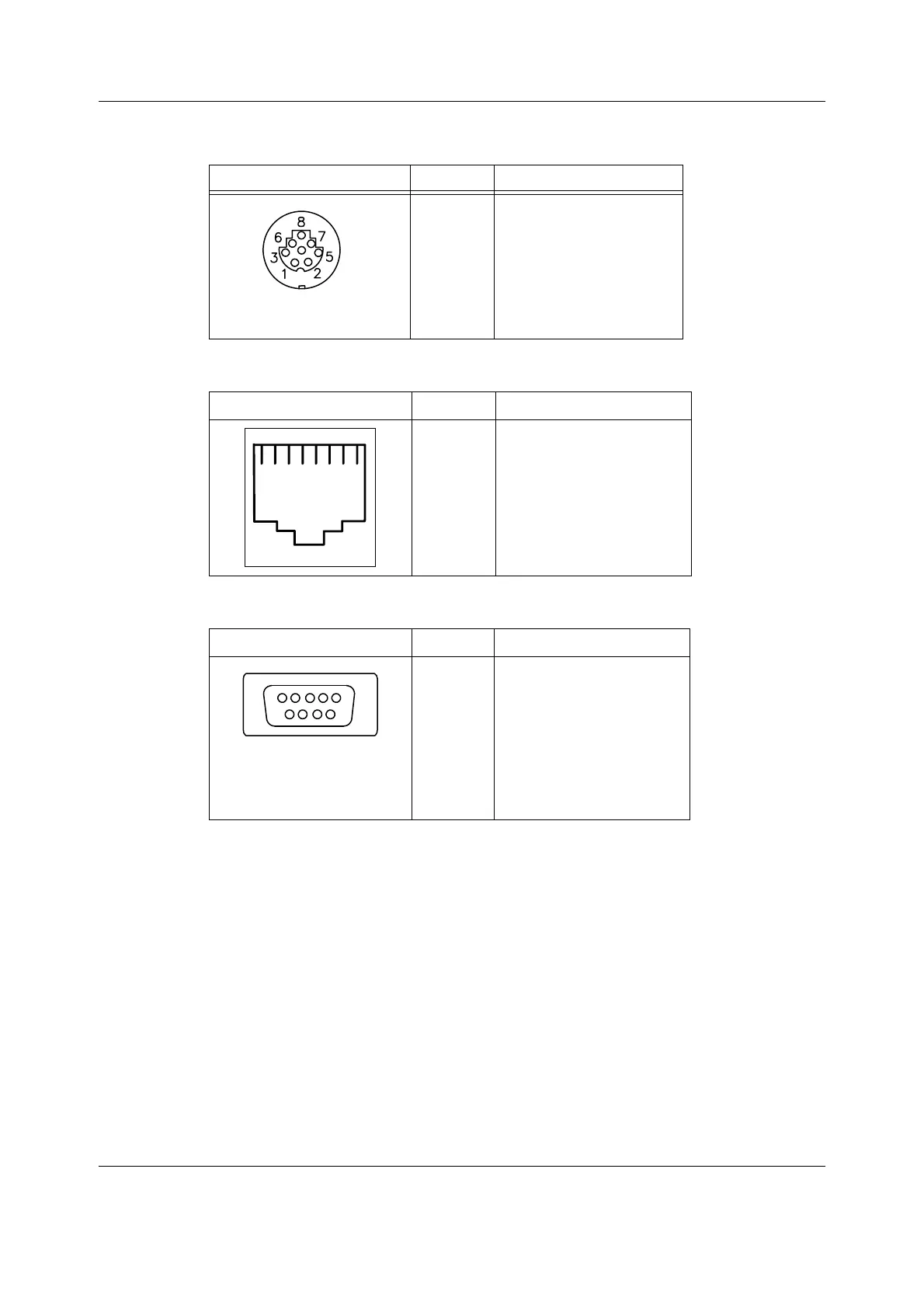
DIS connector, X5 DIS interface
Network connector, X5
Coding element connector, X4
Direct ECG (pin 7)
Delay (max.): 15 ms
Gain ECG (in)/ECG (out): 1 mV/1V
NOTE: The direct ECG out signal is not available with modules M-ESTP rev. 01, M-EST rev. 00 and
M-ETP rev. 00.
Nurse call (pin 8)
The nurse call signal is generated by the red and yellow alarms. When activated, the signal is
set to the high state and remains at the high state until the alarm situation is over or the
SILENCE ALARM key is pressed. The high state range is from 2.8 to 5 V, while the low state
range is from 0 to 0.8 V.
If the output signals are used simultaneously with the coding element, a B-UPINET Y-cable
(order number 889308) should be used.
RS422 connector Pin No. Signal
1
2
3
4
5
6
7
8
DIS_out +
DIS_out -
15V_DIS
GND
8V_DIS
GND
DIS_in +
DIS_in -
RJ45 connector Pin No. Signal
1
2
3
4
5
6
7
8
Tx +
Tx -
Rx +
N/C
N/C
Rx -
N/C
N/C
9 pin female D-connector Pin No. Signal
1
2
3
4
5
6
7
8
9
IDCS1 (chip select)
IDCL (clock)
IDDI (data in)
IDDO (data out)
IDPE (protect enable)
+5Vdc
Direct ECG
Nurse call
GND

 Loading...


