Frame Unit for F-CM(C)1 (Rev. 05), F-CM(C)REC1 (Rev. 01)
5
Document no. M1144958-001
2.3 PMB (Power Management Board)
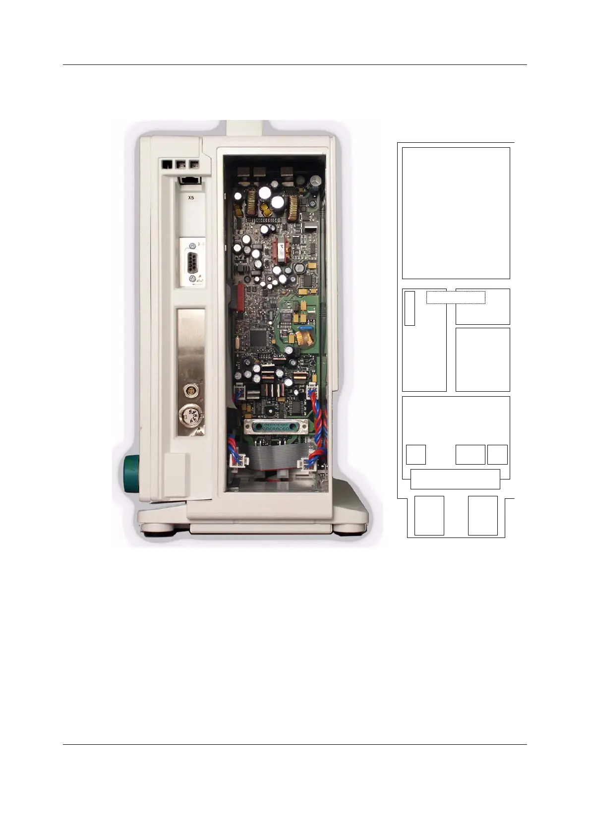
Figure 2 Location of the Power Management Board (side frame panel
removed) and the PMB block diagram
The Power Management Board (PMB) is responsible for distributing DC current for the rest of
the frame. The power source can be the AC/DC unit or one of the internal batteries, and the
chosen power line is referred to as ‘VBUS’. The voltage of VBUS is 10-17V. PMB also controls
the fan voltage and battery charging.
The blocks in “Figure 2” represent different functions on the board.
Module power supply
This block generates the voltages needed for the parameter modules from the selected power
source (VBUS), and delivers those to the module motherboard through connector X3. These
voltages are +5V, +15V, -15V and +15Vdirty.
Module power supply
CPU unit
Battery
charger
supply
PMB +5V supply
Power path switching
electronics
Fan
power
supply
DU
conn.
X9
AC/DC
conn.
X10
Sideplate connector (D-
15, X6)
Battery #1
connector
Battery #2
connector
Signals to
DU,X4
Module motherboard
conn. X3

 Loading...


