System installation
21
Document no. M1144951-004
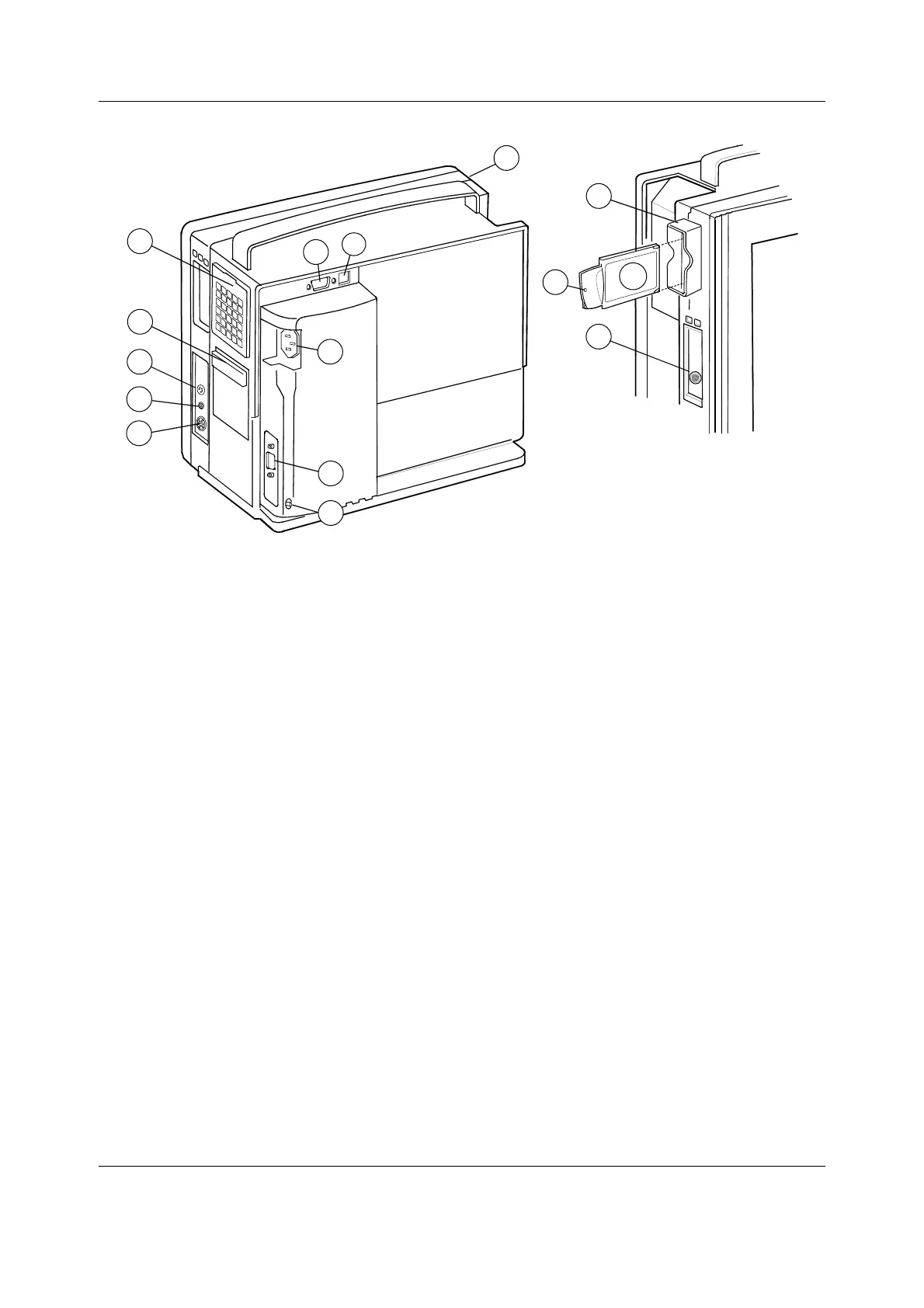
Figure 6 External connections of Compact Monitor frame F-CM(C)1 rev.00...03
(1) Dust filters
(2) Recorder unit (optional)
(3) Connector for factory use only
(4) Synchronization connector
(5) Connector for external keyboard (anesthesia record keeping solution keyboard),
K-CREMCO or Barcode Reader
(6) Potential equalization connector
(7) Serial port connector
(8) Receptacle for power cord
(9) NET ID connector
(10) NET connector
(11) WLAN antenna cover (optional)
(12) Connector for Device Interface Solution
(13) WLAN antenna card LED
WLAN antenna card (optional)
CAUTION Switch the power to standby before making any connections.
3.3.2 Connecting to mains
Connect the power cord to the mains power inlet on the side of the power supply unit and to
the wall socket.
NOTE: Before taking the monitor into use for the first time, the batteries should be fully
charged. Keep the monitor connected to the mains until the Battery charging symbol

 Loading...


