Datex-Ohmeda S/5 Compact Anesthesia and Compact Critical Care Monitors
4
Document no. M1144958-001
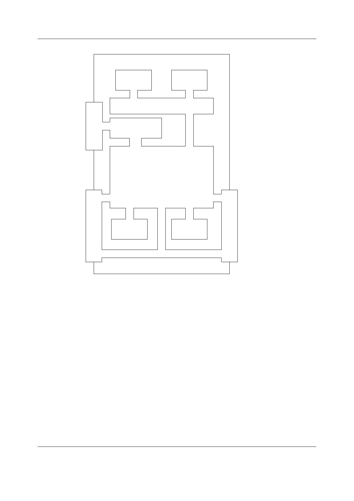
Figure 1 Frame block diagram
2.1 PMB connector board
The PMB connector boards are small boards connected together by a ribbon cable and are
both equipped with the D-25 connectors, one for AC/DC unit and the other for the Display Unit.
The board with the Display Unit connector has also a 16-pin connector for the PMB board.
The PMB connector boards route signals between the AC/DC unit, PMB board and Display Unit.
Signals are transferred via a ribbon cable between the D-connector boards (connected to the
AC/DC and DU). Power lines are transferred separately through the PMB.
2.2 Connector board PMB-REC
The connector board PMB-REC is the one mounted in the Side Frame unit, and connected to
the PMB board via a 15-pin D-connector when inserted into the frame. The connector board
PMB-REC routes operating voltage and signals for the frame cooling fan and for the recorder
unit (optional).
PMB board
Battery #1 Battery #2
Fan
Sideplate connector board
Recorder
25-pin D-connector
25-pin D-connector
CM1 frame
Module
motherboard
Module
connectors
CM1_frame_block_diag.vsd

 Loading...


