1-2 750/760 Feeder Management Relay GE Multilin
1.2 USING THE RELAY 1 GETTING STARTED
1
1.2USING THE RELAY 1.2.1 MENU NAVIGATION
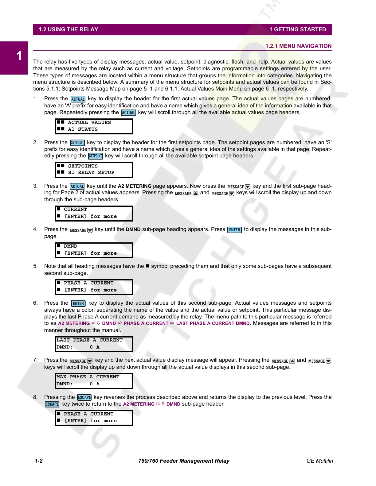
The relay has five types of display messages: actual value, setpoint, diagnostic, flash, and help. Actual values are values
that are measured by the relay such as current and voltage. Setpoints are programmable settings entered by the user.
These types of messages are located within a menu structure that groups the information into categories. Navigating the
menu structure is described below. A summary of the menu structure for setpoints and actual values can be found in Sec-
tions 5.1.1: Setpoints Message Map on page 5–1 and 6.1.1: Actual Values Main Menu on page 6–1, respectively.
1. Press the key to display the header for the first actual values page. The actual values pages are numbered,
have an 'A' prefix for easy identification and have a name which gives a general idea of the information available in that
page. Repeatedly pressing the key will scroll through all the available actual values page headers.
2. Press the key to display the header for the first setpoints page. The setpoint pages are numbered, have an 'S'
prefix for easy identification and have a name which gives a general idea of the settings available in that page. Repeat-
edly pressing the key will scroll through all the available setpoint page headers.
3. Press the key until the
A2 METERING page appears. Now press the key and the first sub-page head-
ing for Page 2 of actual values appears. Pressing the and keys will scroll the display up and down
through the sub-page headers.
4. Press the key until the
DMND sub-page heading appears. Press to display the messages in this sub-
page.
5. Note that all heading messages have the symbol preceding them and that only some sub-pages have a subsequent
second sub-page.
6. Press the key to display the actual values of this second sub-page. Actual values messages and setpoints
always have a colon separating the name of the value and the actual value or setpoint. This particular message dis-
plays the last Phase A current demand as measured by the relay. The menu path to this particular message is referred
to as
A2 METERING ÖØ DMND Ö PHASE A CURRENT Ö LAST PHASE A CURRENT DMND. Messages are referred to in this
manner throughout the manual.
7. Press the key and the next actual value display message will appear. Pressing the and
keys will scroll the display up and down through all the actual value displays in this second sub-page.
8. Pressing the key reverses the process described above and returns the display to the previous level. Press the
key twice to return to the
A2 METERING ÖØ DMND sub-page header.
ACTUAL VALUES
A1 STATUS
SETPOINTS
S1 RELAY SETUP
CURRENT
[ENTER] for more
DMND
[ENTER] for more
PHASE A CURRENT
[ENTER] for more
LAST PHASE A CURRENT
DMND: 0 A
MAX PHASE A CURRENT
DMND: 0 A
PHASE A CURRENT
[ENTER] for more
ACTUAL
ACTUAL
SETPOINT
SETPOINT
ACTUAL
MESSAGE
MESSAGE
MESSAGE
MESSAGE
ENTER
ENTER
MESSAGE
MESSAGE
MESSAGE
ESCAPE
ESCAPE
Courtesy of NationalSwitchgear.com
 Loading...


