GE Multilin 750/760 Feeder Management Relay 5-75
5 SETPOINTS 5.7 S6 MONITORING
5
5.7.2 POWER FACTOR
PATH: SETPOINTS ÖØ S6 MONITORING ÖØ PWR FACTOR Ö PWR FACTOR 1(2)
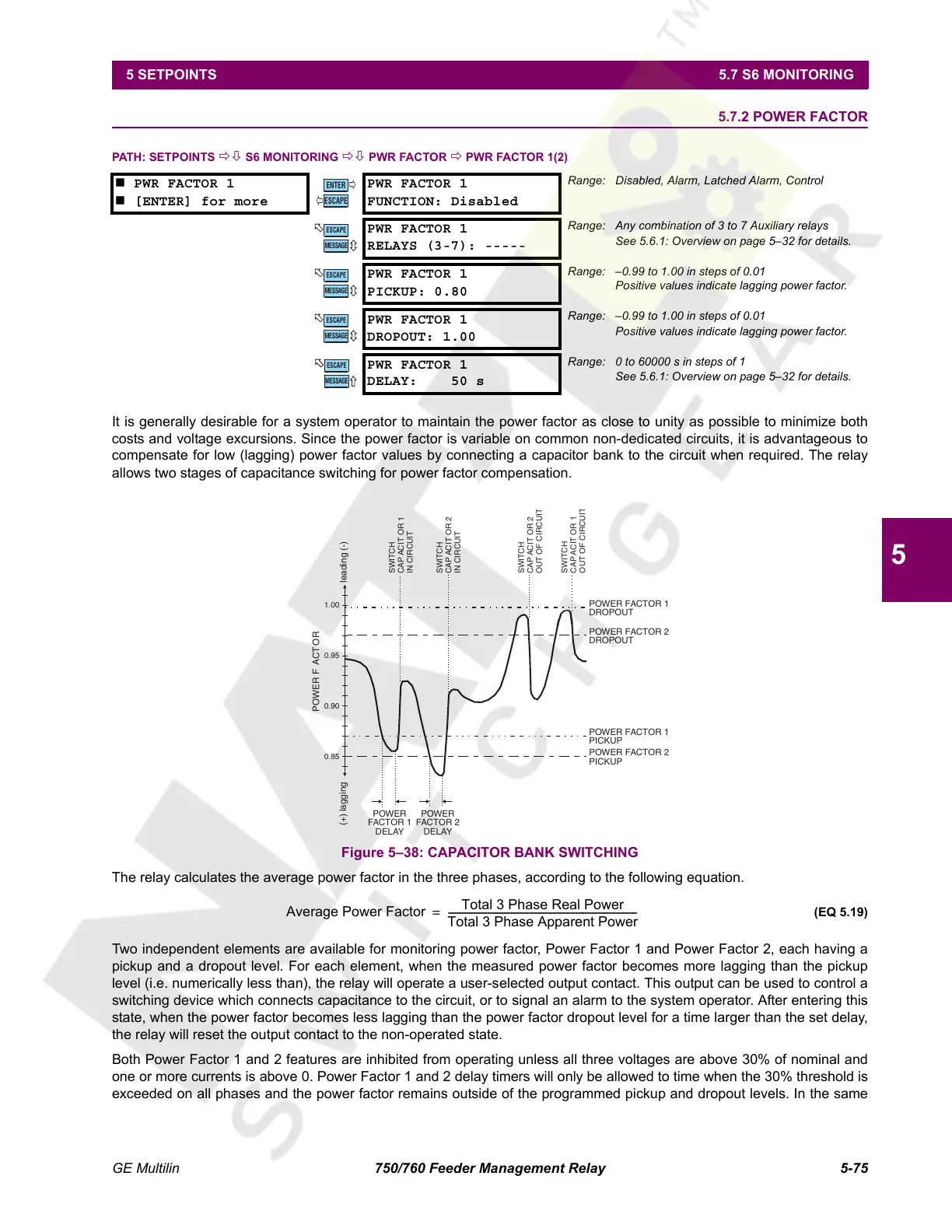
It is generally desirable for a system operator to maintain the power factor as close to unity as possible to minimize both
costs and voltage excursions. Since the power factor is variable on common non-dedicated circuits, it is advantageous to
compensate for low (lagging) power factor values by connecting a capacitor bank to the circuit when required. The relay
allows two stages of capacitance switching for power factor compensation.
Figure 5–38: CAPACITOR BANK SWITCHING
The relay calculates the average power factor in the three phases, according to the following equation.
(EQ 5.19)
Two independent elements are available for monitoring power factor, Power Factor 1 and Power Factor 2, each having a
pickup and a dropout level. For each element, when the measured power factor becomes more lagging than the pickup
level (i.e. numerically less than), the relay will operate a user-selected output contact. This output can be used to control a
switching device which connects capacitance to the circuit, or to signal an alarm to the system operator. After entering this
state, when the power factor becomes less lagging than the power factor dropout level for a time larger than the set delay,
the relay will reset the output contact to the non-operated state.
Both Power Factor 1 and 2 features are inhibited from operating unless all three voltages are above 30% of nominal and
one or more currents is above 0. Power Factor 1 and 2 delay timers will only be allowed to time when the 30% threshold is
exceeded on all phases and the power factor remains outside of the programmed pickup and dropout levels. In the same
PWR FACTOR 1
[ENTER] for more
PWR FACTOR 1
FUNCTION: Disabled
Range: Disabled, Alarm, Latched Alarm, Control
PWR FACTOR 1
RELAYS (3-7): -----
Range: Any combination of 3 to 7 Auxiliary relays
See 5.6.1: Overview on page 5–32 for details.
PWR FACTOR 1
PICKUP: 0.80
Range: –0.99 to 1.00 in steps of 0.01
Positive values indicate lagging power factor.
PWR FACTOR 1
DROPOUT: 1.00
Range: –0.99 to 1.00 in steps of 0.01
Positive values indicate lagging power factor.
PWR FACTOR 1
DELAY: 50 s
Range: 0 to 60000 s in steps of 1
See 5.6.1: Overview on page 5–32 for details.
ENTER
ESCAPE
ð
ð
MESSAGE
ESCAPE
MESSAGE
ESCAPE
MESSAGE
ESCAPE
MESSAGE
ESCAPE
1.00
0.90
0.95
0.85
POWER F
ACT
OR
(+) lagging
leading (-)
POWER
FACTOR 1
DELAY
POWER
FACTOR 2
DELAY
POWER FACTOR 1
DROPOUT
POWER FACTOR 2
DROPOUT
POWER FACTOR 1
PICKUP
SWITCH
CAP
ACIT
OR 1
IN CIRCUIT
POWER FACTOR 2
PICKUP
SWITCH
CAP
ACIT
OR 2
IN CIRCUIT
SWITCH
CAP
ACIT
OR 2
OUT OF CIRCUI
SWITCH
CAP
ACIT
OR 1
OUT OF CIRCUI
Average Power Factor
Total 3 Phase Real Power
Total 3 Phase Apparent Power
---------------------------------------------------------------------------------=
Courtesy of NationalSwitchgear.com
 Loading...


