7-8 750/760 Feeder Management Relay GE Multilin
7.3 MODBUS OPERATIONS 7 COMMUNICATIONS
7
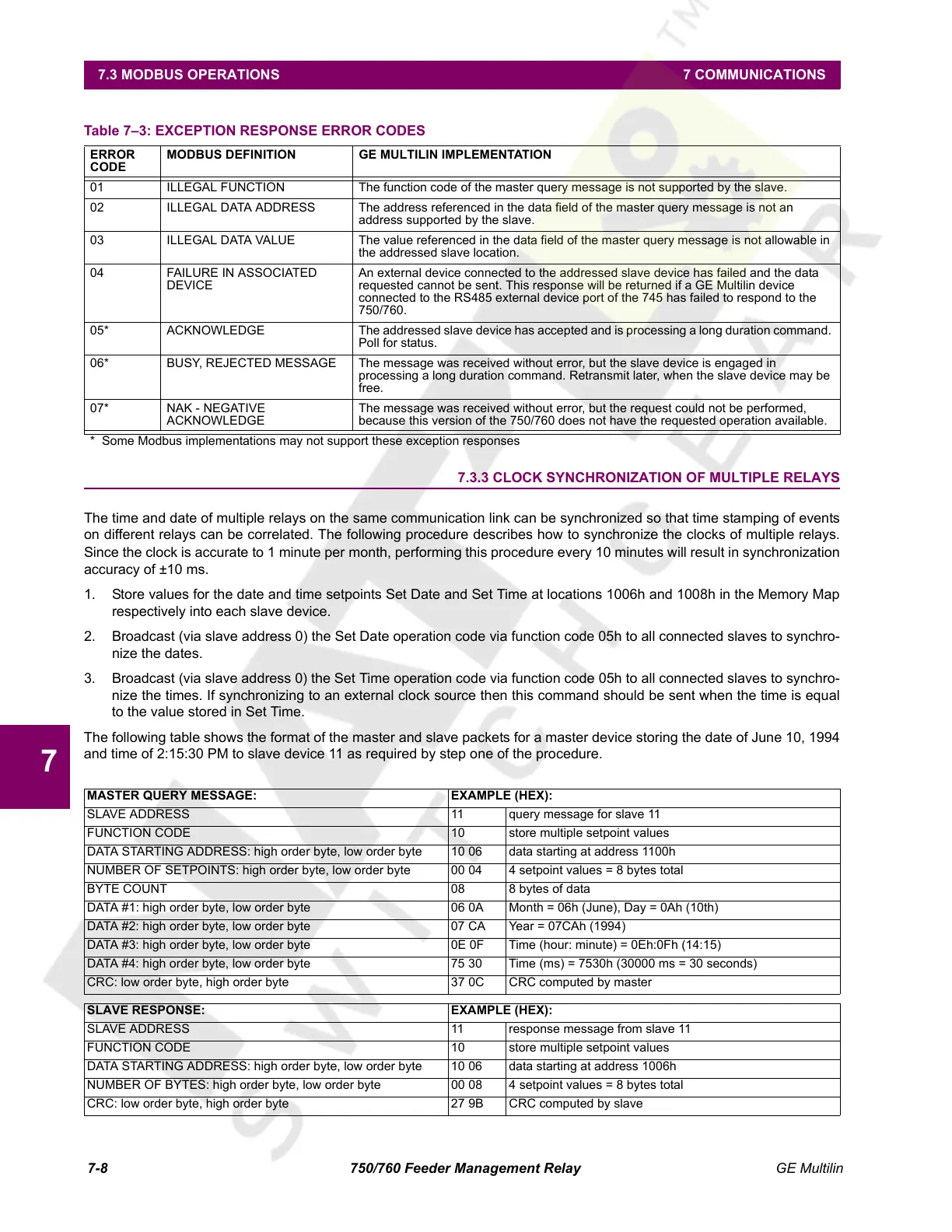
7.3.3 CLOCK SYNCHRONIZATION OF MULTIPLE RELAYS
The time and date of multiple relays on the same communication link can be synchronized so that time stamping of events
on different relays can be correlated. The following procedure describes how to synchronize the clocks of multiple relays.
Since the clock is accurate to 1 minute per month, performing this procedure every 10 minutes will result in synchronization
accuracy of ±10 ms.
1. Store values for the date and time setpoints Set Date and Set Time at locations 1006h and 1008h in the Memory Map
respectively into each slave device.
2. Broadcast (via slave address 0) the Set Date operation code via function code 05h to all connected slaves to synchro-
nize the dates.
3. Broadcast (via slave address 0) the Set Time operation code via function code 05h to all connected slaves to synchro-
nize the times. If synchronizing to an external clock source then this command should be sent when the time is equal
to the value stored in Set Time.
The following table shows the format of the master and slave packets for a master device storing the date of June 10, 1994
and time of 2:15:30 PM to slave device 11 as required by step one of the procedure.
Table 7–3: EXCEPTION RESPONSE ERROR CODES
ERROR
CODE
MODBUS DEFINITION GE MULTILIN IMPLEMENTATION
01 ILLEGAL FUNCTION The function code of the master query message is not supported by the slave.
02 ILLEGAL DATA ADDRESS The address referenced in the data field of the master query message is not an
address supported by the slave.
03 ILLEGAL DATA VALUE The value referenced in the data field of the master query message is not allowable in
the addressed slave location.
04 FAILURE IN ASSOCIATED
DEVICE
An external device connected to the addressed slave device has failed and the data
requested cannot be sent. This response will be returned if a GE Multilin device
connected to the RS485 external device port of the 745 has failed to respond to the
750/760.
05* ACKNOWLEDGE The addressed slave device has accepted and is processing a long duration command.
Poll for status.
06* BUSY, REJECTED MESSAGE The message was received without error, but the slave device is engaged in
processing a long duration command. Retransmit later, when the slave device may be
free.
07* NAK - NEGATIVE
ACKNOWLEDGE
The message was received without error, but the request could not be performed,
because this version of the 750/760 does not have the requested operation available.
* Some Modbus implementations may not support these exception responses
MASTER QUERY MESSAGE: EXAMPLE (HEX):
SLAVE ADDRESS 11 query message for slave 11
FUNCTION CODE 10 store multiple setpoint values
DATA STARTING ADDRESS: high order byte, low order byte 10 06 data starting at address 1100h
NUMBER OF SETPOINTS: high order byte, low order byte 00 04 4 setpoint values = 8 bytes total
BYTE COUNT 08 8 bytes of data
DATA #1: high order byte, low order byte 06 0A Month = 06h (June), Day = 0Ah (10th)
DATA #2: high order byte, low order byte 07 CA Year = 07CAh (1994)
DATA #3: high order byte, low order byte 0E 0F Time (hour: minute) = 0Eh:0Fh (14:15)
DATA #4: high order byte, low order byte 75 30 Time (ms) = 7530h (30000 ms = 30 seconds)
CRC: low order byte, high order byte 37 0C CRC computed by master
SLAVE RESPONSE: EXAMPLE (HEX):
SLAVE ADDRESS 11 response message from slave 11
FUNCTION CODE 10 store multiple setpoint values
DATA STARTING ADDRESS: high order byte, low order byte 10 06 data starting at address 1006h
NUMBER OF BYTES: high order byte, low order byte 00 08 4 setpoint values = 8 bytes total
CRC: low order byte, high order byte 27 9B CRC computed by slave
Courtesy of NationalSwitchgear.com
 Loading...


