GE Multilin 750/760 Feeder Management Relay 5-13
5 SETPOINTS 5.2 S1 RELAY SETUP
5
be reserved for capturing the next event. The TRIGGER POSITION setpoint selects the amount of each buffer to be allocated
for pre-trigger data. If set to "0%", data collection effectively starts once the trigger occurs. If set to 100%, only pre-trigger
data will be recorded in the buffer.
If a trigger occurs before the programmed amount of pre-trigger data is collected, the remainder of the buffer will be
filled with post-trigger data until it is full. Actual values in the memory map provide information as to where the true
trigger position is in each log buffer.
The
TRIGGER ON <EventType> setpoints select specific event types to trigger new waveform captures and are applicable only
when the data logger is operating in trigger mode. The CHNL 1 SOURCE to CHNL 8 SOURCE setpoints can be assigned any
value assignable as an Analog Output parameter. See Table 5–16: Analog Output Parameters on page 5–87 for a list of
values.
If all Channel Sources (1 through 8) are set to "Disabled", then the data logger will not collect data in continuous
mode or respond to triggers in trigger mode.
5.2.7 FRONT PANEL
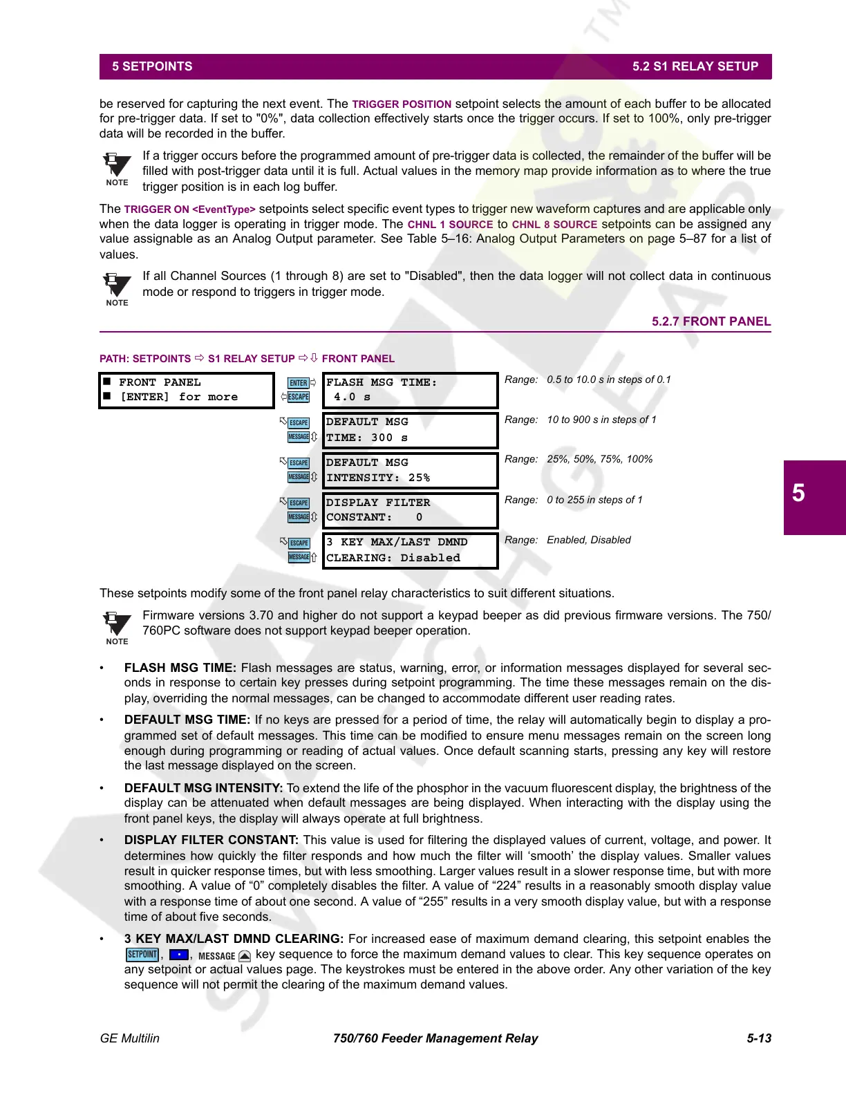
PATH: SETPOINTS Ö S1 RELAY SETUP ÖØ FRONT PANEL
These setpoints modify some of the front panel relay characteristics to suit different situations.
Firmware versions 3.70 and higher do not support a keypad beeper as did previous firmware versions. The 750/
760PC software does not support keypad beeper operation.
• FLASH MSG TIME: Flash messages are status, warning, error, or information messages displayed for several sec-
onds in response to certain key presses during setpoint programming. The time these messages remain on the dis-
play, overriding the normal messages, can be changed to accommodate different user reading rates.
• DEFAULT MSG TIME: If no keys are pressed for a period of time, the relay will automatically begin to display a pro-
grammed set of default messages. This time can be modified to ensure menu messages remain on the screen long
enough during programming or reading of actual values. Once default scanning starts, pressing any key will restore
the last message displayed on the screen.
• DEFAULT MSG INTENSITY: To extend the life of the phosphor in the vacuum fluorescent display, the brightness of the
display can be attenuated when default messages are being displayed. When interacting with the display using the
front panel keys, the display will always operate at full brightness.
• DISPLAY FILTER CONSTANT: This value is used for filtering the displayed values of current, voltage, and power. It
determines how quickly the filter responds and how much the filter will ‘smooth’ the display values. Smaller values
result in quicker response times, but with less smoothing. Larger values result in a slower response time, but with more
smoothing. A value of “0” completely disables the filter. A value of “224” results in a reasonably smooth display value
with a response time of about one second. A value of “255” results in a very smooth display value, but with a response
time of about five seconds.
• 3 KEY MAX/LAST DMND CLEARING: For increased ease of maximum demand clearing, this setpoint enables the
, , key sequence to force the maximum demand values to clear. This key sequence operates on
any setpoint or actual values page. The keystrokes must be entered in the above order. Any other variation of the key
sequence will not permit the clearing of the maximum demand values.
FRONT PANEL
[ENTER] for more
FLASH MSG TIME:
4.0 s
Range: 0.5 to 10.0 s in steps of 0.1
DEFAULT MSG
TIME: 300 s
Range: 10 to 900 s in steps of 1
DEFAULT MSG
INTENSITY: 25%
Range: 25%, 50%, 75%, 100%
DISPLAY FILTER
CONSTANT: 0
Range: 0 to 255 in steps of 1
3 KEY MAX/LAST DMND
CLEARING: Disabled
Range: Enabled, Disabled
NOTE
NOTE
ENTER
ESCAPE
ð
ð
MESSAGE
ESCAPE
MESSAGE
ESCAPE
MESSAGE
ESCAPE
MESSAGE
ESCAPE
NOTE
SETPOINT
MESSAGE
Courtesy of NationalSwitchgear.com
 Loading...


