5-88 750/760 Feeder Management Relay GE Multilin
5.7 S6 MONITORING 5 SETPOINTS
5
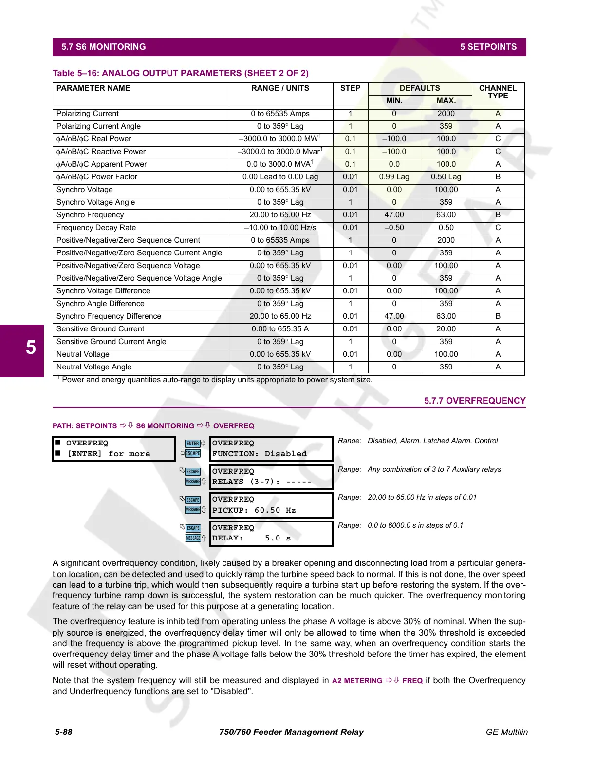
5.7.7 OVERFREQUENCY
PATH: SETPOINTS ÖØ S6 MONITORING ÖØ OVERFREQ
A significant overfrequency condition, likely caused by a breaker opening and disconnecting load from a particular genera-
tion location, can be detected and used to quickly ramp the turbine speed back to normal. If this is not done, the over speed
can lead to a turbine trip, which would then subsequently require a turbine start up before restoring the system. If the over-
frequency turbine ramp down is successful, the system restoration can be much quicker. The overfrequency monitoring
feature of the relay can be used for this purpose at a generating location.
The overfrequency feature is inhibited from operating unless the phase A voltage is above 30% of nominal. When the sup-
ply source is energized, the overfrequency delay timer will only be allowed to time when the 30% threshold is exceeded
and the frequency is above the programmed pickup level. In the same way, when an overfrequency condition starts the
overfrequency delay timer and the phase A voltage falls below the 30% threshold before the timer has expired, the element
will reset without operating.
Note that the system frequency will still be measured and displayed in
A2 METERING ÖØ FREQ if both the Overfrequency
and Underfrequency functions are set to "Disabled".
Polarizing Current 0 to 65535 Amps 1 0 2000 A
Polarizing Current Angle 0 to 359° Lag 1 0 359 A
φA/φB/φC Real Power –3000.0 to 3000.0 MW
1
0.1 –100.0 100.0 C
φA/φB/φC Reactive Power –3000.0 to 3000.0 Mvar
1
0.1 –100.0 100.0 C
φA/φB/φC Apparent Power 0.0 to 3000.0 MVA
1
0.1 0.0 100.0 A
φA/φB/φC Power Factor 0.00 Lead to 0.00 Lag 0.01 0.99 Lag 0.50 Lag B
Synchro Voltage 0.00 to 655.35 kV 0.01 0.00 100.00 A
Synchro Voltage Angle 0 to 359° Lag 1 0 359 A
Synchro Frequency 20.00 to 65.00 Hz 0.01 47.00 63.00 B
Frequency Decay Rate –10.00 to 10.00 Hz/s 0.01 –0.50 0.50 C
Positive/Negative/Zero Sequence Current 0 to 65535 Amps 1 0 2000 A
Positive/Negative/Zero Sequence Current Angle 0 to 359° Lag 1 0 359 A
Positive/Negative/Zero Sequence Voltage 0.00 to 655.35 kV 0.01 0.00 100.00 A
Positive/Negative/Zero Sequence Voltage Angle 0 to 359° Lag 1 0 359 A
Synchro Voltage Difference 0.00 to 655.35 kV 0.01 0.00 100.00 A
Synchro Angle Difference 0 to 359° Lag 1 0 359 A
Synchro Frequency Difference 20.00 to 65.00 Hz 0.01 47.00 63.00 B
Sensitive Ground Current 0.00 to 655.35 A 0.01 0.00 20.00 A
Sensitive Ground Current Angle 0 to 359° Lag 1 0 359 A
Neutral Voltage 0.00 to 655.35 kV 0.01 0.00 100.00 A
Neutral Voltage Angle 0 to 359° Lag 1 0 359 A
OVERFREQ
[ENTER] for more
OVERFREQ
FUNCTION: Disabled
Range: Disabled, Alarm, Latched Alarm, Control
OVERFREQ
RELAYS (3-7): -----
Range: Any combination of 3 to 7 Auxiliary relays
OVERFREQ
PICKUP: 60.50 Hz
Range: 20.00 to 65.00 Hz in steps of 0.01
OVERFREQ
DELAY: 5.0 s
Range: 0.0 to 6000.0 s in steps of 0.1
Table 5–16: ANALOG OUTPUT PARAMETERS (SHEET 2 OF 2)
PARAMETER NAME RANGE / UNITS STEP DEFAULTS CHANNEL
TYPE
MIN. MAX.
1
Power and energy quantities auto-range to display units appropriate to power system size.
ENTER
ESCAPE
ð
ð
MESSAGE
ESCAPE
MESSAGE
ESCAPE
MESSAGE
ESCAPE
Courtesy of NationalSwitchgear.com
 Loading...


