GE Multilin 750/760 Feeder Management Relay 2-3
2 INTRODUCTION 2.1 OVERVIEW
2
2.1.2 THEORY OF OPERATION
Relay functions are controlled by two processors: a Motorola 68332 32-bit microprocessor measures all analog signals and
logic inputs, outputs all analog signals, and controls all output relays; an Intel 80C186 16-bit microprocessor reads all user
input including communications, and outputs to the faceplate display and LEDs. The processors pass information to each
other via an RS485 serial communications channel. The remainder of this section describes the algorithms and operations
that are critical to protection elements.
CURRENT AND VOLTAGE WAVEFORM CAPTURE:
Current and voltage transformers (CTs and VTs) are used to scale-down the incoming current and voltage signals from the
source instrument transformers. The current and voltage signals are then passed through a 400 Hz low pass anti-aliasing
filter. All signals are then simultaneously captured by sample and hold buffers to ensure there are no phase shifts. The sig-
nals are converted to digital values by a 12-bit A/D converter before finally being passed on to the 68332 CPU for analysis.
Both current and voltage are sampled sixteen times per power frequency cycle with frequency tracking control. These ‘raw’
samples are calibrated in software and then placed into the waveform capture buffer thus emulating a fault recorder. The
waveforms can be retrieved from the relay via the 750/760PC software for display and diagnostics.
FREQUENCY TRACKING:
Frequency measurement is done by measuring the time between zero crossings of the Bus VT A and Line VT voltage
inputs. Both signals are passed through a 72 Hz low pass filter to prevent false zero crossings. Frequency readings are dis-
carded if the rate of change between two successive cycles is greater than 10 Hz/second. This prevents momentary false
frequency readings due to noise, phase reversals, or faults.
Frequency tracking utilizes the measured frequency to set the sampling rate for current and voltage which results in better
accuracy for the FFT algorithm for off-nominal frequencies. Also, sampling is synchronized to the Va-x voltage zero cross-
ing which results in better co-ordination for multiple 750/760 relays on the same bus. If a stable frequency signal is not
available then the sampling rate defaults to the nominal system frequency.
PHASORS, TRANSIENTS, AND HARMONICS:
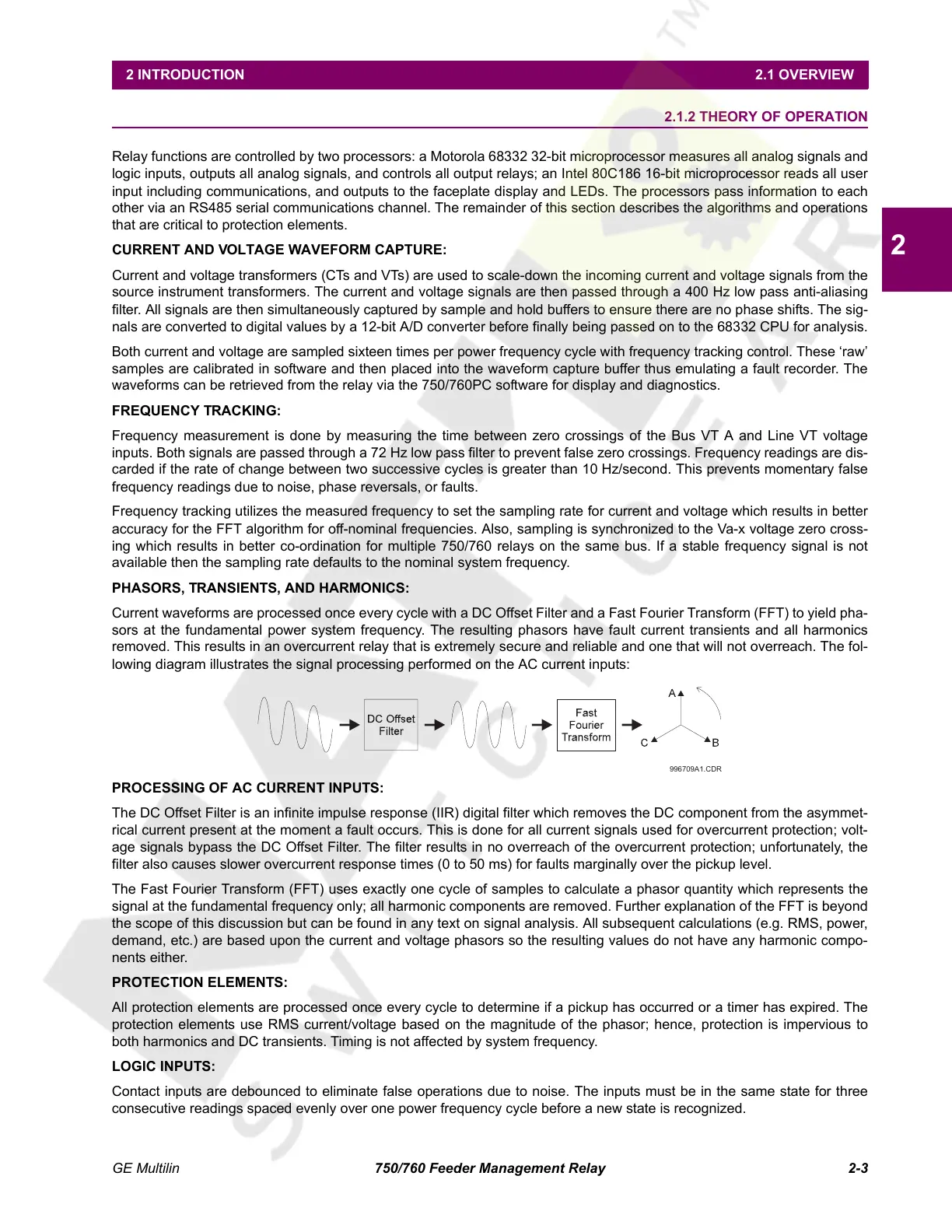
Current waveforms are processed once every cycle with a DC Offset Filter and a Fast Fourier Transform (FFT) to yield pha-
sors at the fundamental power system frequency. The resulting phasors have fault current transients and all harmonics
removed. This results in an overcurrent relay that is extremely secure and reliable and one that will not overreach. The fol-
lowing diagram illustrates the signal processing performed on the AC current inputs:
PROCESSING OF AC CURRENT INPUTS:
The DC Offset Filter is an infinite impulse response (IIR) digital filter which removes the DC component from the asymmet-
rical current present at the moment a fault occurs. This is done for all current signals used for overcurrent protection; volt-
age signals bypass the DC Offset Filter. The filter results in no overreach of the overcurrent protection; unfortunately, the
filter also causes slower overcurrent response times (0 to 50 ms) for faults marginally over the pickup level.
The Fast Fourier Transform (FFT) uses exactly one cycle of samples to calculate a phasor quantity which represents the
signal at the fundamental frequency only; all harmonic components are removed. Further explanation of the FFT is beyond
the scope of this discussion but can be found in any text on signal analysis. All subsequent calculations (e.g. RMS, power,
demand, etc.) are based upon the current and voltage phasors so the resulting values do not have any harmonic compo-
nents either.
PROTECTION ELEMENTS:
All protection elements are processed once every cycle to determine if a pickup has occurred or a timer has expired. The
protection elements use RMS current/voltage based on the magnitude of the phasor; hence, protection is impervious to
both harmonics and DC transients. Timing is not affected by system frequency.
LOGIC INPUTS:
Contact inputs are debounced to eliminate false operations due to noise. The inputs must be in the same state for three
consecutive readings spaced evenly over one power frequency cycle before a new state is recognized.
996709A1.CDR
Courtesy of NationalSwitchgear.com
 Loading...


