GE Multilin 750/760 Feeder Management Relay 5-99
5 SETPOINTS 5.8 S7 CONTROL
5
5.8.2 SYNCHROCHECK
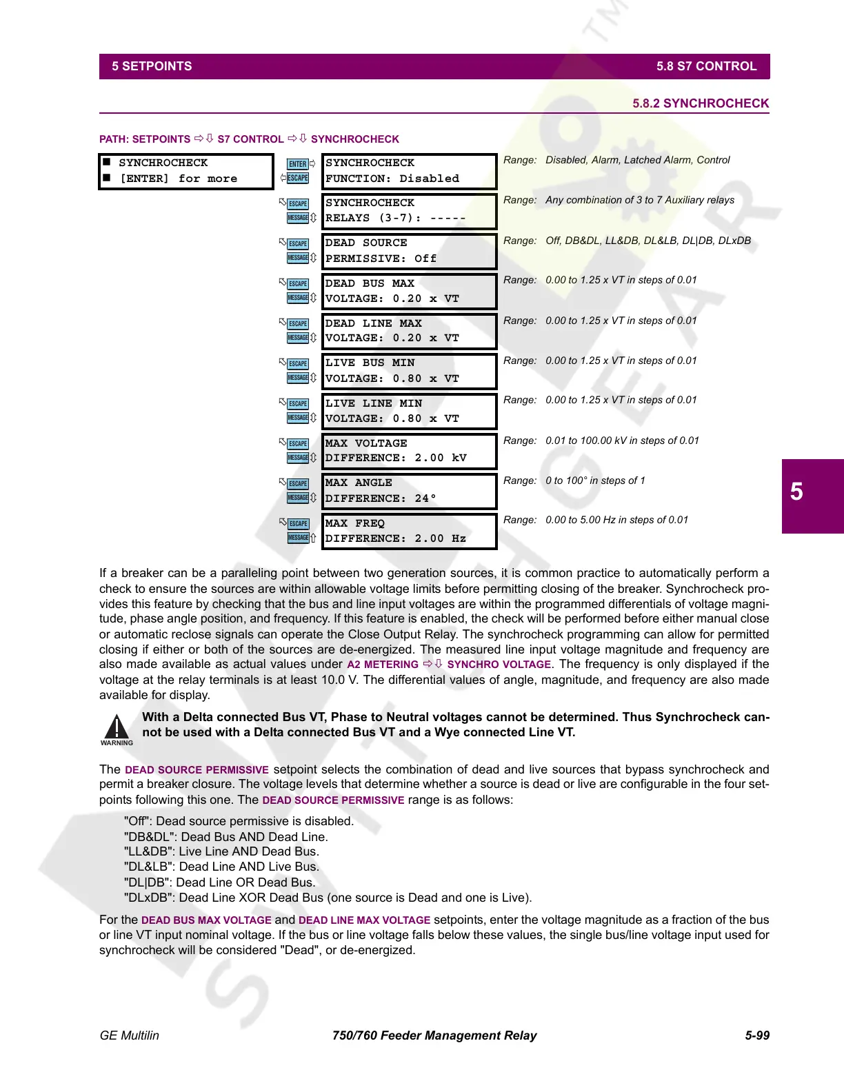
PATH: SETPOINTS ÖØ S7 CONTROL ÖØ SYNCHROCHECK
If a breaker can be a paralleling point between two generation sources, it is common practice to automatically perform a
check to ensure the sources are within allowable voltage limits before permitting closing of the breaker. Synchrocheck pro-
vides this feature by checking that the bus and line input voltages are within the programmed differentials of voltage magni-
tude, phase angle position, and frequency. If this feature is enabled, the check will be performed before either manual close
or automatic reclose signals can operate the Close Output Relay. The synchrocheck programming can allow for permitted
closing if either or both of the sources are de-energized. The measured line input voltage magnitude and frequency are
also made available as actual values under
A2 METERING ÖØ SYNCHRO VOLTAGE. The frequency is only displayed if the
voltage at the relay terminals is at least 10.0 V. The differential values of angle, magnitude, and frequency are also made
available for display.
With a Delta connected Bus VT, Phase to Neutral voltages cannot be determined. Thus Synchrocheck can-
not be used with a Delta connected Bus VT and a Wye connected Line VT.
The
DEAD SOURCE PERMISSIVE setpoint selects the combination of dead and live sources that bypass synchrocheck and
permit a breaker closure. The voltage levels that determine whether a source is dead or live are configurable in the four set-
points following this one. The
DEAD SOURCE PERMISSIVE range is as follows:
"Off": Dead source permissive is disabled.
"DB&DL": Dead Bus AND Dead Line.
"LL&DB": Live Line AND Dead Bus.
"DL&LB": Dead Line AND Live Bus.
"DL|DB": Dead Line OR Dead Bus.
"DLxDB": Dead Line XOR Dead Bus (one source is Dead and one is Live).
For the
DEAD BUS MAX VOLTAGE and DEAD LINE MAX VOLTAGE setpoints, enter the voltage magnitude as a fraction of the bus
or line VT input nominal voltage. If the bus or line voltage falls below these values, the single bus/line voltage input used for
synchrocheck will be considered "Dead", or de-energized.
SYNCHROCHECK
[ENTER] for more
SYNCHROCHECK
FUNCTION: Disabled
Range: Disabled, Alarm, Latched Alarm, Control
SYNCHROCHECK
RELAYS (3-7): -----
Range: Any combination of 3 to 7 Auxiliary relays
DEAD SOURCE
PERMISSIVE: Off
Range: Off, DB&DL, LL&DB, DL&LB, DL|DB, DLxDB
DEAD BUS MAX
VOLTAGE: 0.20 x VT
Range: 0.00 to 1.25 x VT in steps of 0.01
DEAD LINE MAX
VOLTAGE: 0.20 x VT
Range: 0.00 to 1.25 x VT in steps of 0.01
LIVE BUS MIN
VOLTAGE: 0.80 x VT
Range: 0.00 to 1.25 x VT in steps of 0.01
LIVE LINE MIN
VOLTAGE: 0.80 x VT
Range: 0.00 to 1.25 x VT in steps of 0.01
MAX VOLTAGE
DIFFERENCE: 2.00 kV
Range: 0.01 to 100.00 kV in steps of 0.01
MAX ANGLE
DIFFERENCE: 24°
Range: 0 to 100° in steps of 1
MAX FREQ
DIFFERENCE: 2.00 Hz
Range: 0.00 to 5.00 Hz in steps of 0.01
ENTER
ESCAPE
ð
ð
MESSAGE
ESCAPE
MESSAGE
ESCAPE
MESSAGE
ESCAPE
MESSAGE
ESCAPE
MESSAGE
ESCAPE
MESSAGE
ESCAPE
MESSAGE
ESCAPE
MESSAGE
ESCAPE
MESSAGE
ESCAPE
WARNING
Courtesy of NationalSwitchgear.com
 Loading...


