5-12 750/760 Feeder Management Relay GE Multilin
5.2 S1 RELAY SETUP 5 SETPOINTS
5
5.2.6 DATA LOGGER
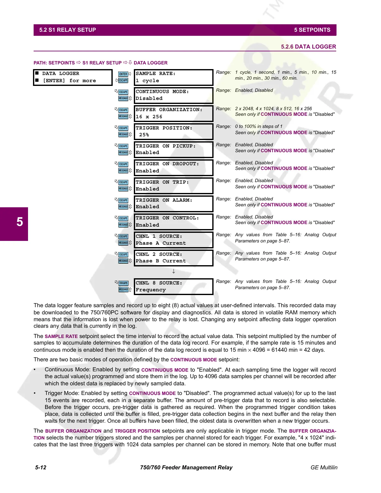
PATH: SETPOINTS Ö S1 RELAY SETUP ÖØ DATA LOGGER
The data logger feature samples and record up to eight (8) actual values at user-defined intervals. This recorded data may
be downloaded to the 750/760PC software for display and diagnostics. All data is stored in volatile RAM memory which
means that the information is lost when power to the relay is lost. Changing any setpoint affecting data logger operation
clears any data that is currently in the log.
The
SAMPLE RATE setpoint select the time interval to record the actual value data. This setpoint multiplied by the number of
samples to accumulate determines the duration of the data log record. For example, if the sample rate is 15 minutes and
continuous mode is enabled then the duration of the data log record is equal to 15 min × 4096 = 61440 min = 42 days.
There are two basic modes of operation defined by the
CONTINUOUS MODE setpoint:
• Continuous Mode: Enabled by setting
CONTINUOUS MODE to "Enabled". At each sampling time the logger will record
the actual value(s) programmed and store them in the log. Up to 4096 data samples per channel will be recorded after
which the oldest data is replaced by newly sampled data.
• Trigger Mode: Enabled by setting
CONTINUOUS MODE to "Disabled". The programmed actual value(s) for up to the last
15 events are recorded, each in a separate buffer. The amount of pre-trigger data that to record is also selectable.
Before the trigger occurs, pre-trigger data is gathered as required. When the programmed trigger condition takes
place, data is collected until the buffer is filled, pre-trigger data collection begins in the next buffer and the relay then
waits for the next trigger. Once all buffers have been filled, the oldest data is overwritten when a new trigger occurs.
The
BUFFER ORGANIZATION and TRIGGER POSITION setpoints are only applicable in trigger mode. The BUFFER ORGANZIA-
TION
selects the number triggers stored and the samples per channel stored for each trigger. For example, "4 x 1024" indi-
cates that the last three triggers with 1024 data samples per channel can be stored in memory. Note that one buffer must
DATA LOGGER
[ENTER] for more
SAMPLE RATE:
1 cycle
Range: 1 cycle, 1 second, 1 min., 5 min., 10 min., 15
min., 20 min., 30 min., 60 min.
CONTINUOUS MODE:
Disabled
Range: Enabled, Disabled
BUFFER ORGANIZATION:
16 x 256
Range: 2 x 2048, 4 x 1024, 8 x 512, 16 x 256
Seen only if CONTINUOUS MODE is "Disabled"
TRIGGER POSITION:
25%
Range: 0 to 100% in steps of 1
Seen only if CONTINUOUS MODE is "Disabled"
TRIGGER ON PICKUP:
Enabled
Range: Enabled, Disabled
Seen only if CONTINUOUS MODE is "Disabled"
TRIGGER ON DROPOUT:
Enabled
Range: Enabled, Disabled
Seen only if CONTINUOUS MODE is "Disabled"
TRIGGER ON TRIP:
Enabled
Range: Enabled, Disabled
Seen only if CONTINUOUS MODE is "Disabled"
TRIGGER ON ALARM:
Enabled
Range: Enabled, Disabled
Seen only if CONTINUOUS MODE is "Disabled"
TRIGGER ON CONTROL:
Enabled
Range: Enabled, Disabled
Seen only if CONTINUOUS MODE is "Disabled"
CHNL 1 SOURCE:
Phase A Current
Range: Any values from Table 5–16: Analog Output
Parameters on page 5–87.
CHNL 2 SOURCE:
Phase B Current
Range: Any values from Table 5–16: Analog Output
Parameters on page 5–87.
↓
CHNL 8 SOURCE:
Frequency
Range: Any values from Table 5–16: Analog Output
Parameters on page 5–87.
ENTER
ESCAPE
ð
ð
MESSAGE
ESCAPE
MESSAGE
ESCAPE
MESSAGE
ESCAPE
MESSAGE
ESCAPE
MESSAGE
ESCAPE
MESSAGE
ESCAPE
MESSAGE
ESCAPE
MESSAGE
ESCAPE
MESSAGE
ESCAPE
MESSAGE
ESCAPE
MESSAGE
ESCAPE
Courtesy of NationalSwitchgear.com
 Loading...


