7-12 750/760 Feeder Management Relay GE Multilin
7.3 MODBUS OPERATIONS 7 COMMUNICATIONS
7
The User Memory Map is only intended to be used to READ data in a proficient manner for the master computer.
The communication system should not be configured in a manner that generates WRITES to these locations con-
tinuously, as these settings are stored in the EEPROM that has a maximum of 100000 program/erase cycles.
7.3.8 MEMORY MAP ORGANIZATION
The 750/760 Memory Map describes all the data registers that can be accessed via serial communications. The Memory
Map address range is grouped into several categories as outlined in the following table. All memory map locations are two
byte (16 bit) values. The remaining pages of this chapter list all locations of the Memory Map. Addresses for all locations
are shown in hexadecimal. Consult the range, step, units, and the data format (listed after the memory map) to interpret
register values.
Many Modbus communications drivers add 40001d to the actual address of the register addresses. For example, if
address 0h was to be read, then 40001d would be the address required by the Modbus communications driver;
similarly, if address 320h (800d) was to be read, then 40801d would be the address required by the Modbus com-
munications driver.
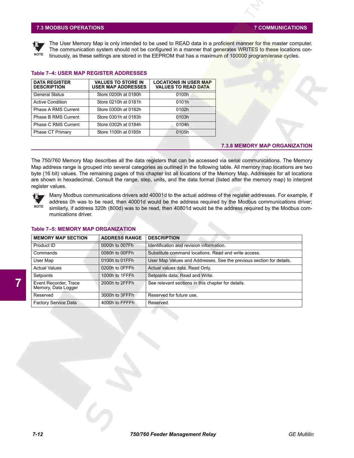
Table 7–4: USER MAP REGISTER ADDRESSES
DATA REGISTER
DESCRIPTION
VALUES TO STORE IN
USER MAP ADDRESSES
LOCATIONS IN USER MAP
VALUES TO READ DATA
General Status Store 0200h at 0180h 0100h
Active Condition Store 0210h at 0181h 0101h
Phase A RMS Current Store 0300h at 0182h 0102h
Phase B RMS Current Store 0301h at 0183h 0103h
Phase C RMS Current Store 0302h at 0184h 0104h
Phase CT Primary Store 1100h at 0185h 0105h
Table 7–5: MEMORY MAP ORGANIZATION
MEMORY MAP SECTION ADDRESS RANGE DESCRIPTION
Product ID 0000h to 007Fh Identification and revision information.
Commands 0080h to 00FFh Substitute command locations. Read and write access.
User Map 0100h to 01FFh User Map Values and Addresses. See the previous section for details.
Actual Values 0200h to 0FFFh Actual values data. Read Only.
Setpoints 1000h to 1FFFh Setpoints data. Read and Write.
Event Recorder, Trace
Memory, Data Logger
2000h to 2FFFh See relevant sections in this chapter for details.
Reserved 3000h to 3FFFh Reserved for future use.
Factory Service Data 4000h to FFFFh Reserved.
NOTE
NOTE
Courtesy of NationalSwitchgear.com
 Loading...


