5-10 750/760 Feeder Management Relay GE Multilin
5.2 S1 RELAY SETUP 5 SETPOINTS
5
5.2.3 CLOCK
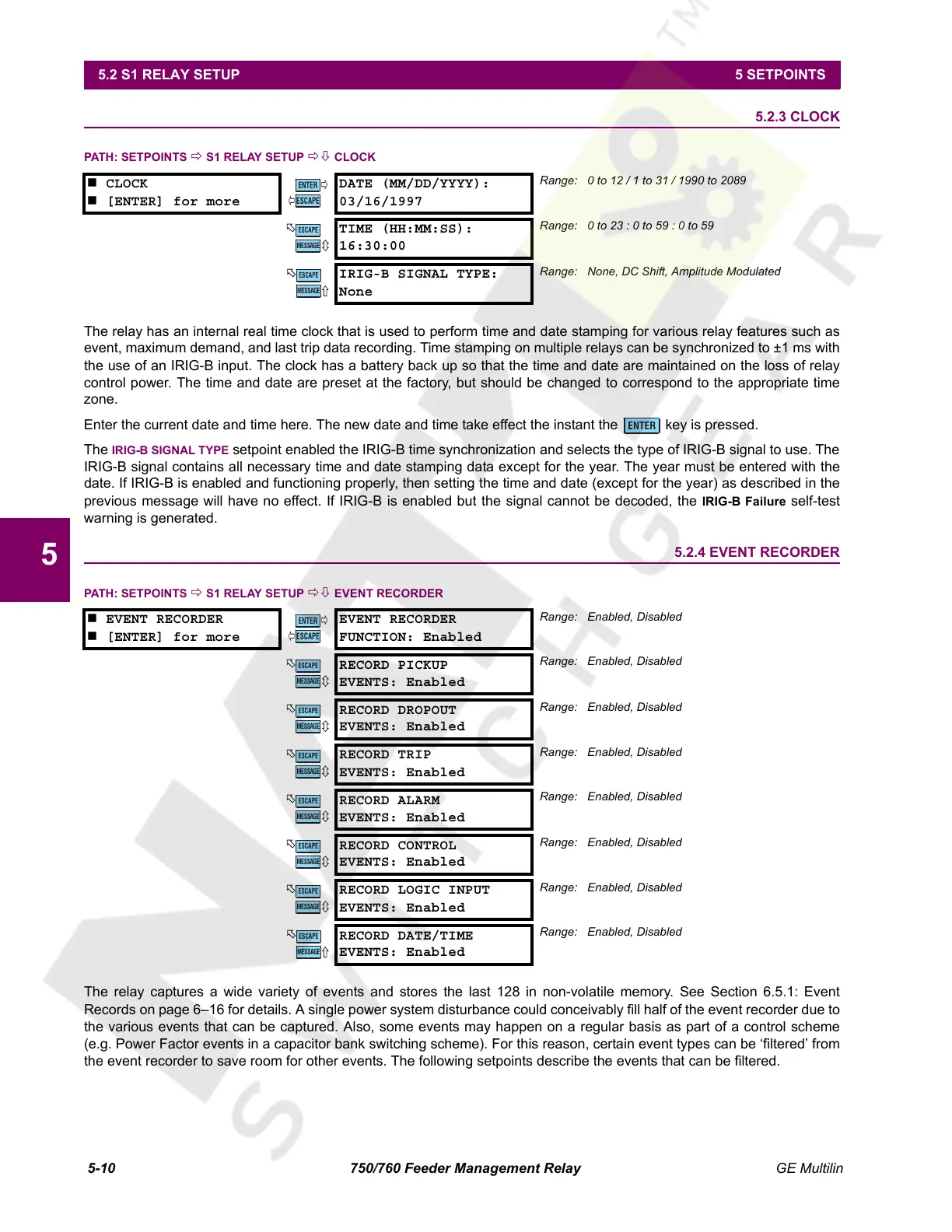
PATH: SETPOINTS Ö S1 RELAY SETUP ÖØ CLOCK
The relay has an internal real time clock that is used to perform time and date stamping for various relay features such as
event, maximum demand, and last trip data recording. Time stamping on multiple relays can be synchronized to ±1 ms with
the use of an IRIG-B input. The clock has a battery back up so that the time and date are maintained on the loss of relay
control power. The time and date are preset at the factory, but should be changed to correspond to the appropriate time
zone.
Enter the current date and time here. The new date and time take effect the instant the key is pressed.
The
IRIG-B SIGNAL TYPE setpoint enabled the IRIG-B time synchronization and selects the type of IRIG-B signal to use. The
IRIG-B signal contains all necessary time and date stamping data except for the year. The year must be entered with the
date. If IRIG-B is enabled and functioning properly, then setting the time and date (except for the year) as described in the
previous message will have no effect. If IRIG-B is enabled but the signal cannot be decoded, the
IRIG-B Failure self-test
warning is generated.
5.2.4 EVENT RECORDER
PATH: SETPOINTS Ö S1 RELAY SETUP ÖØ EVENT RECORDER
The relay captures a wide variety of events and stores the last 128 in non-volatile memory. See Section 6.5.1: Event
Records on page 6–16 for details. A single power system disturbance could conceivably fill half of the event recorder due to
the various events that can be captured. Also, some events may happen on a regular basis as part of a control scheme
(e.g. Power Factor events in a capacitor bank switching scheme). For this reason, certain event types can be ‘filtered’ from
the event recorder to save room for other events. The following setpoints describe the events that can be filtered.
CLOCK
[ENTER] for more
DATE (MM/DD/YYYY):
03/16/1997
Range: 0 to 12 / 1 to 31 / 1990 to 2089
TIME (HH:MM:SS):
16:30:00
Range: 0 to 23 : 0 to 59 : 0 to 59
IRIG-B SIGNAL TYPE:
None
Range: None, DC Shift, Amplitude Modulated
EVENT RECORDER
[ENTER] for more
EVENT RECORDER
FUNCTION: Enabled
Range: Enabled, Disabled
RECORD PICKUP
EVENTS: Enabled
Range: Enabled, Disabled
RECORD DROPOUT
EVENTS: Enabled
Range: Enabled, Disabled
RECORD TRIP
EVENTS: Enabled
Range: Enabled, Disabled
RECORD ALARM
EVENTS: Enabled
Range: Enabled, Disabled
RECORD CONTROL
EVENTS: Enabled
Range: Enabled, Disabled
RECORD LOGIC INPUT
EVENTS: Enabled
Range: Enabled, Disabled
RECORD DATE/TIME
EVENTS: Enabled
Range: Enabled, Disabled
ENTER
ESCAPE
ð
ð
MESSAGE
ESCAPE
MESSAGE
ESCAPE
ENTER
ENTER
ESCAPE
ð
ð
MESSAGE
ESCAPE
MESSAGE
ESCAPE
MESSAGE
ESCAPE
MESSAGE
ESCAPE
MESSAGE
ESCAPE
MESSAGE
ESCAPE
MESSAGE
ESCAPE
Courtesy of NationalSwitchgear.com
 Loading...


