5-86 750/760 Feeder Management Relay GE Multilin
5.7 S6 MONITORING 5 SETPOINTS
5
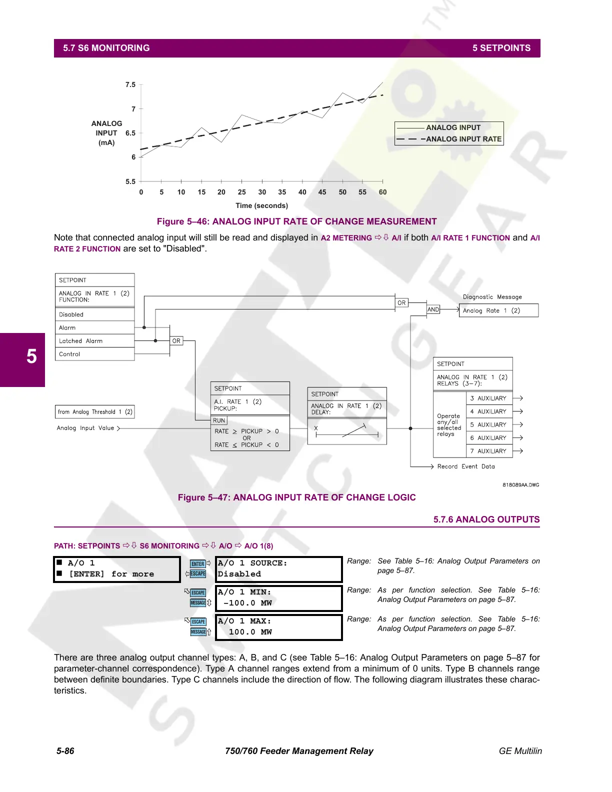
Figure 5–46: ANALOG INPUT RATE OF CHANGE MEASUREMENT
Note that connected analog input will still be read and displayed in A2 METERING ÖØ A/I if both A/I RATE 1 FUNCTION and A/I
RATE 2 FUNCTION are set to "Disabled".
Figure 5–47: ANALOG INPUT RATE OF CHANGE LOGIC
5.7.6 ANALOG OUTPUTS
PATH: SETPOINTS ÖØ S6 MONITORING ÖØ A/O Ö A/O 1(8)
There are three analog output channel types: A, B, and C (see Table 5–16: Analog Output Parameters on page 5–87 for
parameter-channel correspondence). Type A channel ranges extend from a minimum of 0 units. Type B channels range
between definite boundaries. Type C channels include the direction of flow. The following diagram illustrates these charac-
teristics.
A/O 1
[ENTER] for more
A/O 1 SOURCE:
Disabled
Range: See Table 5–16: Analog Output Parameters on
page 5–87.
A/O 1 MIN:
–100.0 MW
Range: As per function selection. See Table 5–16:
Analog Output Parameters on page 5–87.
A/O 1 MAX:
100.0 MW
Range: As per function selection. See Table 5–16:
Analog Output Parameters on page 5–87.
5.5
6
6.5
7
7.5
0510 152025303540 45505560
Time (seconds)
ANALOG
INPUT
(mA)
ANALOG INPUT
ANALOG INPUT RATE
ENTER
ESCAPE
ð
ð
MESSAGE
ESCAPE
MESSAGE
ESCAPE
Courtesy of NationalSwitchgear.com
 Loading...


