6-8 750/760 Feeder Management Relay GE Multilin
6.3 A2 METERING 6 ACTUAL VALUES
6
6.3A2 METERING 6.3.1 METERING CONVENTIONS
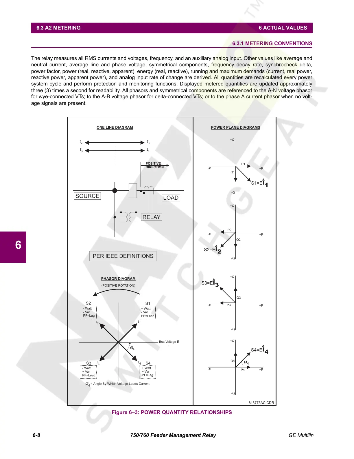
The relay measures all RMS currents and voltages, frequency, and an auxiliary analog input. Other values like average and
neutral current, average line and phase voltage, symmetrical components, frequency decay rate, synchrocheck delta,
power factor, power (real, reactive, apparent), energy (real, reactive), running and maximum demands (current, real power,
reactive power, apparent power), and analog input rate of change are derived. All quantities are recalculated every power
system cycle and perform protection and monitoring functions. Displayed metered quantities are updated approximately
three (3) times a second for readability. All phasors and symmetrical components are referenced to the A-N voltage phasor
for wye-connected VTs; to the A-B voltage phasor for delta-connected VTs; or to the phase A current phasor when no volt-
age signals are present.
Figure 6–3: POWER QUANTITY RELATIONSHIPS
I
2
I
2
I
1
I
1
I
4
I
4
I
3
I
3
+Watt
-Var
PF=Lead
+Q
+Q
+Q
+Q
-Q
-Q
-Q
-Q
Q1
Q2
Q3
Q4
P1
P2
P3
P4
S1=E
I
1
S2=E
I
2
S3=E
I
3
S4=E
I
4
-P
-P
-P
-P
+P
+P
+P
+P
818773AC.CDR
-Watt
-Var
PF=Lag
Bus Voltage E
S2
S1
S4
S3
4
4
POWER PLANE DIAGRAMS
(POSITIVE ROTATION)
PHASOR DIAGRAM
= Angle By Which Voltage Leads Current
4
^
^
^
^
-Watt
+Var
PF=Lead
ONE LINE DIAGRAM
POSITIVE
DIRECTION
SOURCE
LOAD
RELAY
PER IEEE DEFINITIONS
+Watt
+Var
PF=Lag
Courtesy of NationalSwitchgear.com
 Loading...


