GE Multilin 750/760 Feeder Management Relay 3-1
3 INSTALLATION 3.1 MECHANICAL
3
3 INSTALLATION 3.1MECHANICAL 3.1.1 DRAWOUT CASE
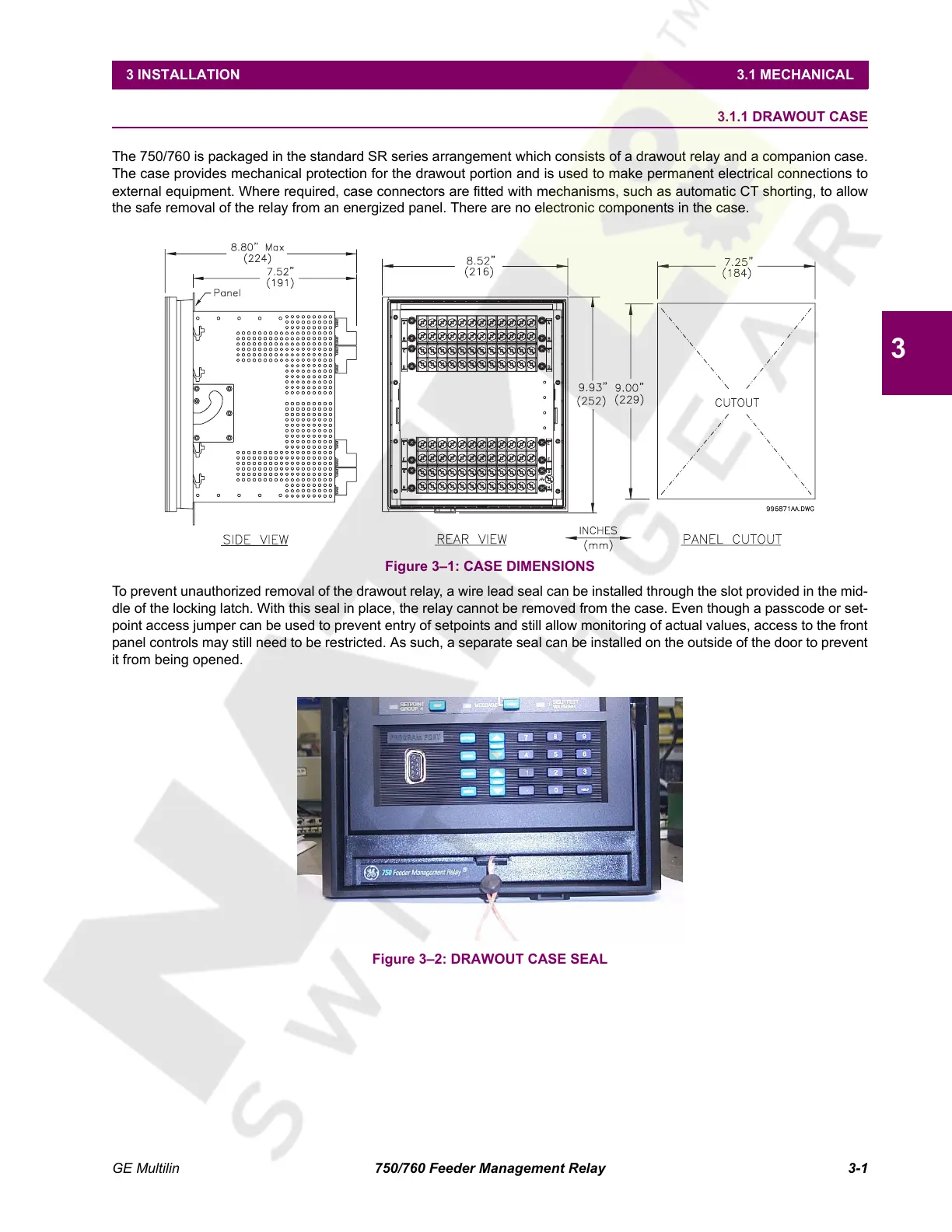
The 750/760 is packaged in the standard SR series arrangement which consists of a drawout relay and a companion case.
The case provides mechanical protection for the drawout portion and is used to make permanent electrical connections to
external equipment. Where required, case connectors are fitted with mechanisms, such as automatic CT shorting, to allow
the safe removal of the relay from an energized panel. There are no electronic components in the case.
Figure 3–1: CASE DIMENSIONS
To prevent unauthorized removal of the drawout relay, a wire lead seal can be installed through the slot provided in the mid-
dle of the locking latch. With this seal in place, the relay cannot be removed from the case. Even though a passcode or set-
point access jumper can be used to prevent entry of setpoints and still allow monitoring of actual values, access to the front
panel controls may still need to be restricted. As such, a separate seal can be installed on the outside of the door to prevent
it from being opened.
Figure 3–2: DRAWOUT CASE SEAL
Courtesy of NationalSwitchgear.com
 Loading...


