3-2 750/760 Feeder Management Relay GE Multilin
3.1 MECHANICAL 3 INSTALLATION
3
3.1.2 INSTALLATION
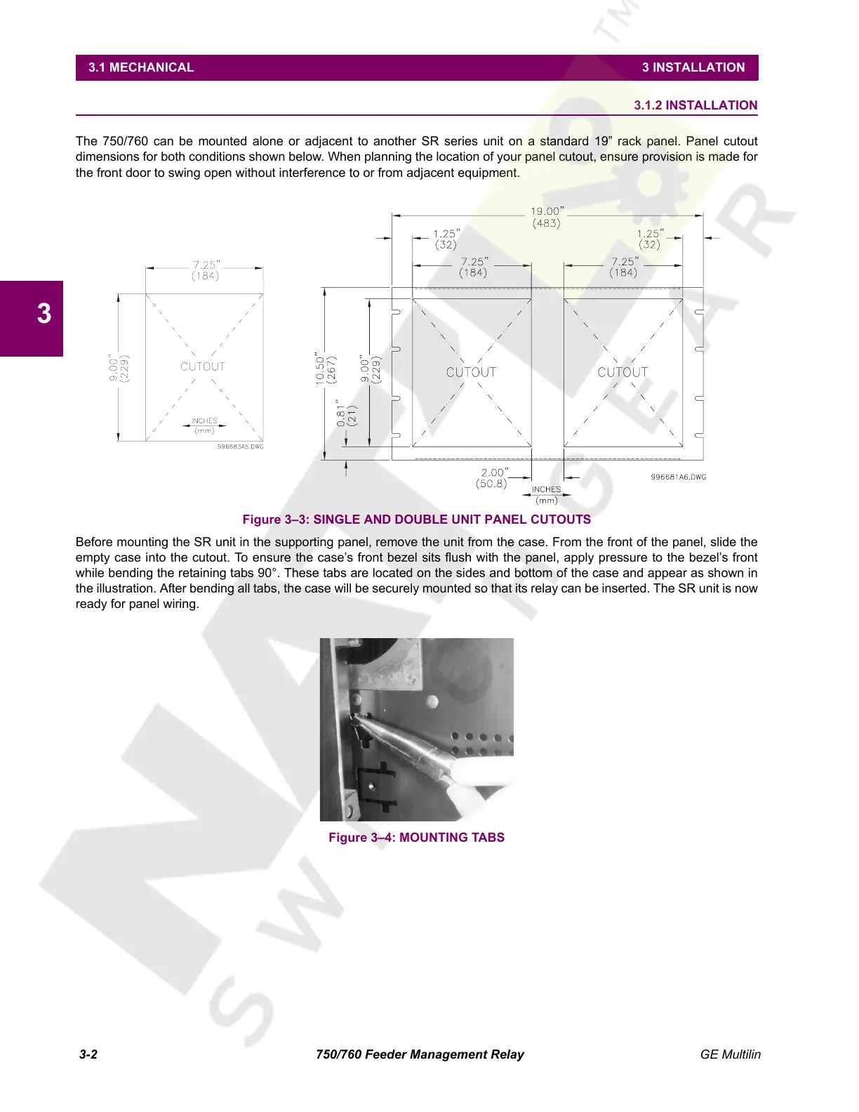
The 750/760 can be mounted alone or adjacent to another SR series unit on a standard 19” rack panel. Panel cutout
dimensions for both conditions shown below. When planning the location of your panel cutout, ensure provision is made for
the front door to swing open without interference to or from adjacent equipment.
Figure 3–3: SINGLE AND DOUBLE UNIT PANEL CUTOUTS
Before mounting the SR unit in the supporting panel, remove the unit from the case. From the front of the panel, slide the
empty case into the cutout. To ensure the case’s front bezel sits flush with the panel, apply pressure to the bezel’s front
while bending the retaining tabs 90°. These tabs are located on the sides and bottom of the case and appear as shown in
the illustration. After bending all tabs, the case will be securely mounted so that its relay can be inserted. The SR unit is now
ready for panel wiring.
Figure 3–4: MOUNTING TABS
Courtesy of NationalSwitchgear.com
 Loading...


