GE Multilin 750/760 Feeder Management Relay 5-131
5 SETPOINTS 5.9 S8 TESTING
5
5.9.4 SIMULATION
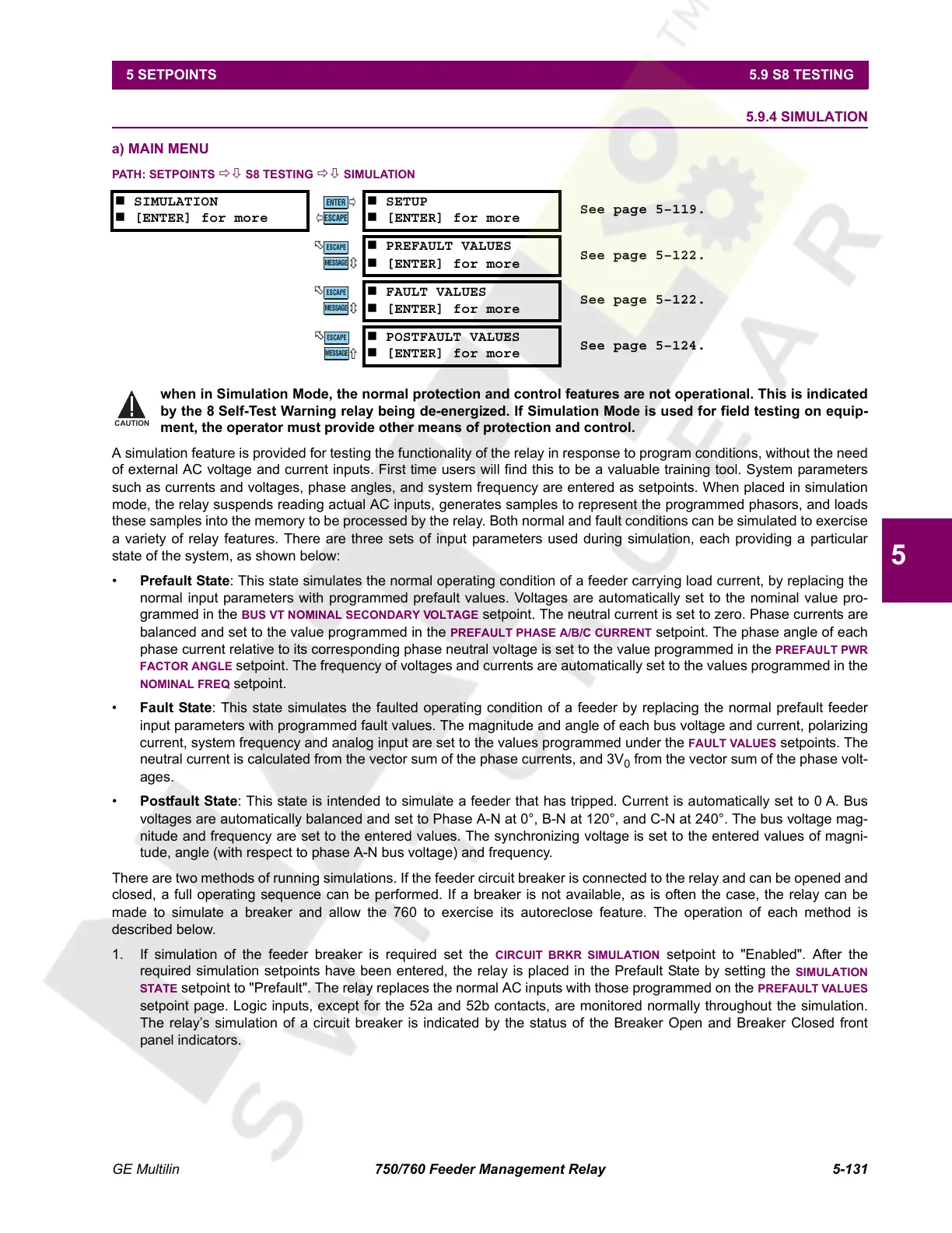
a) MAIN MENU
PATH: SETPOINTS ÖØ S8 TESTING ÖØ SIMULATION
when in Simulation Mode, the normal protection and control features are not operational. This is indicated
by the 8 Self-Test Warning relay being de-energized. If Simulation Mode is used for field testing on equip-
ment, the operator must provide other means of protection and control.
A simulation feature is provided for testing the functionality of the relay in response to program conditions, without the need
of external AC voltage and current inputs. First time users will find this to be a valuable training tool. System parameters
such as currents and voltages, phase angles, and system frequency are entered as setpoints. When placed in simulation
mode, the relay suspends reading actual AC inputs, generates samples to represent the programmed phasors, and loads
these samples into the memory to be processed by the relay. Both normal and fault conditions can be simulated to exercise
a variety of relay features. There are three sets of input parameters used during simulation, each providing a particular
state of the system, as shown below:
• Prefault State: This state simulates the normal operating condition of a feeder carrying load current, by replacing the
normal input parameters with programmed prefault values. Voltages are automatically set to the nominal value pro-
grammed in the
BUS VT NOMINAL SECONDARY VOLTAGE setpoint. The neutral current is set to zero. Phase currents are
balanced and set to the value programmed in the
PREFAULT PHASE A/B/C CURRENT setpoint. The phase angle of each
phase current relative to its corresponding phase neutral voltage is set to the value programmed in the PREFAULT PWR
FACTOR ANGLE setpoint. The frequency of voltages and currents are automatically set to the values programmed in the
NOMINAL FREQ setpoint.
• Fault State: This state simulates the faulted operating condition of a feeder by replacing the normal prefault feeder
input parameters with programmed fault values. The magnitude and angle of each bus voltage and current, polarizing
current, system frequency and analog input are set to the values programmed under the FAULT VALUES setpoints. The
neutral current is calculated from the vector sum of the phase currents, and 3V
0
from the vector sum of the phase volt-
ages.
• Postfault State: This state is intended to simulate a feeder that has tripped. Current is automatically set to 0 A. Bus
voltages are automatically balanced and set to Phase A-N at 0°, B-N at 120°, and C-N at 240°. The bus voltage mag-
nitude and frequency are set to the entered values. The synchronizing voltage is set to the entered values of magni-
tude, angle (with respect to phase A-N bus voltage) and frequency.
There are two methods of running simulations. If the feeder circuit breaker is connected to the relay and can be opened and
closed, a full operating sequence can be performed. If a breaker is not available, as is often the case, the relay can be
made to simulate a breaker and allow the 760 to exercise its autoreclose feature. The operation of each method is
described below.
1. If simulation of the feeder breaker is required set the
CIRCUIT BRKR SIMULATION setpoint to "Enabled". After the
required simulation setpoints have been entered, the relay is placed in the Prefault State by setting the
SIMULATION
STATE
setpoint to "Prefault". The relay replaces the normal AC inputs with those programmed on the PREFAULT VALUES
setpoint page. Logic inputs, except for the 52a and 52b contacts, are monitored normally throughout the simulation.
The relay’s simulation of a circuit breaker is indicated by the status of the Breaker Open and Breaker Closed front
panel indicators.
SIMULATION
[ENTER] for more
SETUP
[ENTER] for more
See page 5–119.
PREFAULT VALUES
[ENTER] for more
See page 5–122.
FAULT VALUES
[ENTER] for more
See page 5–122.
POSTFAULT VALUES
[ENTER] for more
See page 5–124.
ENTER
ESCAPE
ð
ð
MESSAGE
ESCAPE
MESSAGE
ESCAPE
MESSAGE
ESCAPE
CAUTION
Courtesy of NationalSwitchgear.com
 Loading...


