GE Multilin 750/760 Feeder Management Relay 5-119
5 SETPOINTS 5.8 S7 CONTROL
5
If the fault is permanent, subsequent overcurrent element(s) will trip and initiate reclosure. The scheme will eventually go to
lockout when the MAX NUMBER OF RECLOSURE SHOTS has been met and another trip occurs. If a breaker failure condition is
detected at any time during operation, the scheme will again go straight to lockout. When in lockout, the 760 disables the
reclose scheme and returns all protection setpoints to their initial values. To re-enable the autoreclose scheme the relay
must be reset via the front panel reset key, the Reset logic input function, communications, or by a manual close operation.
The latter resets the scheme only after the
AR BLOCK TIME UPON MANUAL CLOSE timer expires, and no overcurrent elements
are active.
If the fault is transient in nature then no overcurrent element(s) will trip after the breaker has closed. The scheme will auto-
matically reset when the reset timer, started upon the first reclosure initiation, exceeds the
AR RESET TIME setpoint value.
This autoreclosure reset returns the shot counter to zero and all protection setpoints to their initial values.
An anti-pumping feature is built into the reset mechanism. Otherwise, breaker pumping could occur when the fault level is
between the initial overcurrent pickup level and the adjusted overcurrent pickup level for a reclosure shot. It prevents a per-
manent fault from continuously repeating the trip breaker, initiate reclose, close breaker, automatic reset of autoreclose
scheme, trip breaker sequence. If this condition is detected the anti-pumping feature returns protection setpoints to their ini-
tial values without resetting the shot counter. The relay will then continue to trip and reclose until lockout is reached.
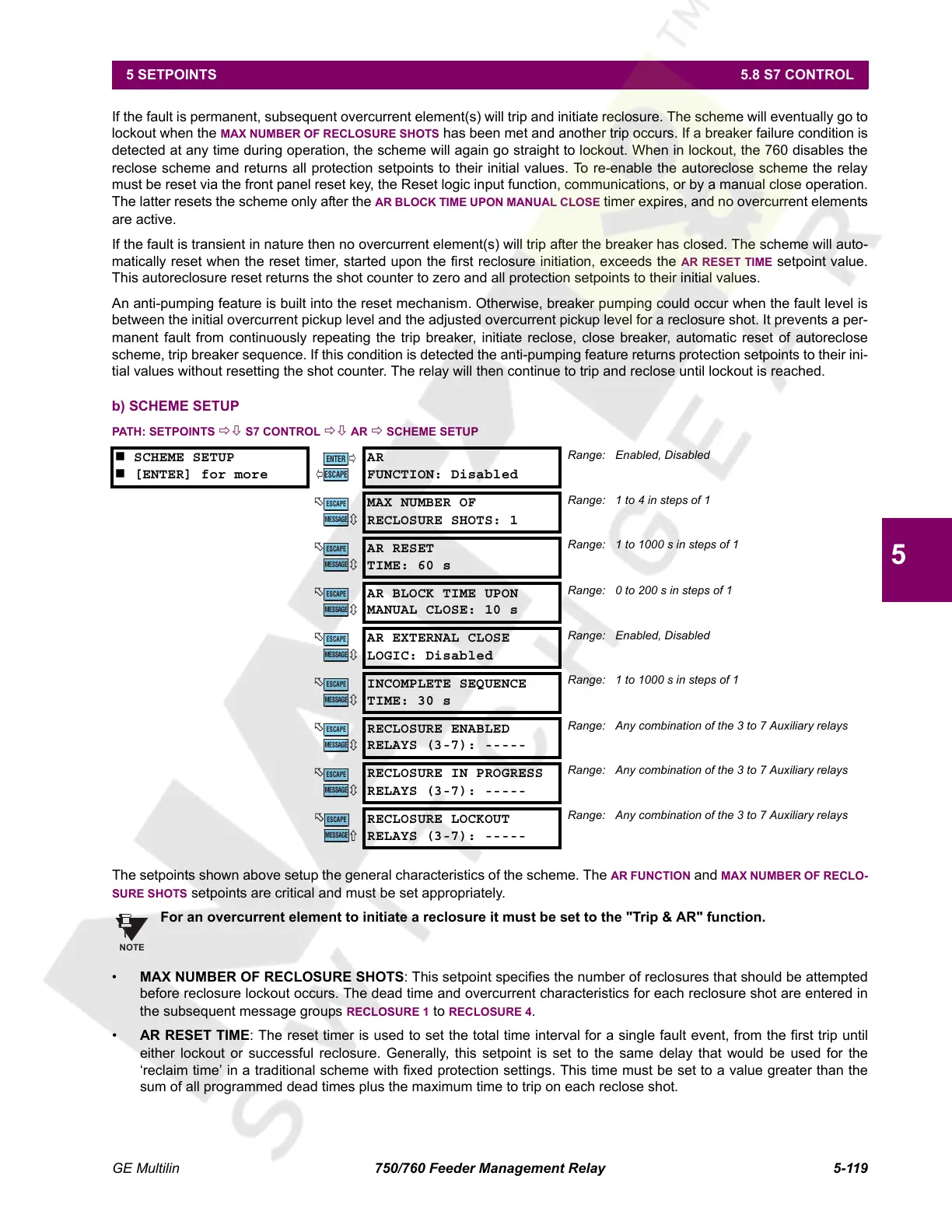
b) SCHEME SETUP
PATH: SETPOINTS ÖØ S7 CONTROL ÖØ AR Ö SCHEME SETUP
The setpoints shown above setup the general characteristics of the scheme. The AR FUNCTION and MAX NUMBER OF RECLO-
SURE SHOTS setpoints are critical and must be set appropriately.
For an overcurrent element to initiate a reclosure it must be set to the "Trip & AR" function.
• MAX NUMBER OF RECLOSURE SHOTS: This setpoint specifies the number of reclosures that should be attempted
before reclosure lockout occurs. The dead time and overcurrent characteristics for each reclosure shot are entered in
the subsequent message groups
RECLOSURE 1 to RECLOSURE 4.
• AR RESET TIME: The reset timer is used to set the total time interval for a single fault event, from the first trip until
either lockout or successful reclosure. Generally, this setpoint is set to the same delay that would be used for the
‘reclaim time’ in a traditional scheme with fixed protection settings. This time must be set to a value greater than the
sum of all programmed dead times plus the maximum time to trip on each reclose shot.
SCHEME SETUP
[ENTER] for more
AR
FUNCTION: Disabled
Range: Enabled, Disabled
MAX NUMBER OF
RECLOSURE SHOTS: 1
Range: 1 to 4 in steps of 1
AR RESET
TIME: 60 s
Range: 1 to 1000 s in steps of 1
AR BLOCK TIME UPON
MANUAL CLOSE: 10 s
Range: 0 to 200 s in steps of 1
AR EXTERNAL CLOSE
LOGIC: Disabled
Range: Enabled, Disabled
INCOMPLETE SEQUENCE
TIME: 30 s
Range: 1 to 1000 s in steps of 1
RECLOSURE ENABLED
RELAYS (3-7): -----
Range: Any combination of the 3 to 7 Auxiliary relays
RECLOSURE IN PROGRESS
RELAYS (3-7): -----
Range: Any combination of the 3 to 7 Auxiliary relays
RECLOSURE LOCKOUT
RELAYS (3-7): -----
Range: Any combination of the 3 to 7 Auxiliary relays
ENTER
ESCAPE
ð
ð
MESSAGE
ESCAPE
MESSAGE
ESCAPE
MESSAGE
ESCAPE
MESSAGE
ESCAPE
MESSAGE
ESCAPE
MESSAGE
ESCAPE
MESSAGE
ESCAPE
MESSAGE
ESCAPE
NOTE
Courtesy of NationalSwitchgear.com
 Loading...


