GE Multilin 750/760 Feeder Management Relay 5-19
5 SETPOINTS 5.4 S3 LOGIC INPUTS
5
5.4S3 LOGIC INPUTS 5.4.1 OVERVIEW
The 750/760 relay has twenty (20) logic inputs which can be used to operate a variety of logic functions for circuit breaker
control, external trips, blocking of protection elements, etc. The relay has ‘contact inputs’ and ‘virtual inputs’ that are com-
bined in a form of programmable logic to facilitate the implementation of various schemes.
The relay has 14 rear terminal contact inputs. These contacts can be either wet or dry (see Section 3.2.7: Logic Inputs on
page 3–14 for typical wiring of the logic input contacts). External contacts are either open or closed and are debounced for
one power frequency cycle to prevent false operation from induced voltage. Because of debouncing, momentary contacts
must have a minimum dwell time greater than one power frequency cycle.
The relay also has twenty (20) virtual inputs which are analogous to software switches. They allow all the functionality of
logic inputs to be invoked via serial communications or from the front panel. This has the following advantages over contact
inputs only:
• The number of logic inputs can be increased without introducing additional hardware.
• Logic functions can be invoked from a remote location over a single RS485 communications channel.
• The same logic function can be invoked both locally via contact input or front panel keypad, and/or remotely via com-
munications.
• Panel switches can be replaced entirely by virtual switches to save cost and wiring.
Virtual inputs are simply memory locations in the relay which can be assigned a value via communications or from the
A1
STATUS ÖØ VIRTUAL INPUTS actual values menu. If the value stored in memory is "0", then the virtual input is Off; otherwise,
the virtual input is On. The state of virtual inputs is written as if it were a setpoint; these values are non-volatile and are
found in memory map locations 0090 to 00A4 hex. Momentary virtual inputs are simulated by first writing a "1" to the corre-
sponding register followed by writing a "0". Due to communications delay there will be a dwell time of 50 to 200 ms. Main-
tained virtual inputs are simulated by writing a "1" to the corresponding register.
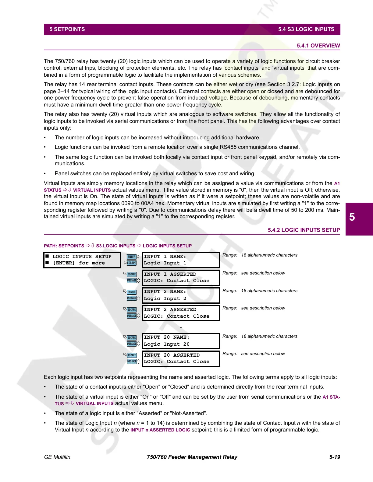
5.4.2 LOGIC INPUTS SETUP
PATH: SETPOINTS ÖØ S3 LOGIC INPUTS Ö LOGIC INPUTS SETUP
Each logic input has two setpoints representing the name and asserted logic. The following terms apply to all logic inputs:
• The state of a contact input is either "Open" or "Closed" and is determined directly from the rear terminal inputs.
• The state of a virtual input is either "On" or "Off" and can be set by the user from serial communications or the
A1 STA-
TUS
ÖØ VIRTUAL INPUTS actual values menu.
• The state of a logic input is either "Asserted" or "Not-Asserted".
• The state of Logic Input n (where n = 1 to 14) is determined by combining the state of Contact Input n with the state of
Virtual Input n according to the
INPUT n ASSERTED LOGIC setpoint; this is a limited form of programmable logic.
LOGIC INPUTS SETUP
[ENTER] for more
INPUT 1 NAME:
Logic Input 1
Range: 18 alphanumeric characters
INPUT 1 ASSERTED
LOGIC: Contact Close
Range: see description below
INPUT 2 NAME:
Logic Input 2
Range: 18 alphanumeric characters
INPUT 2 ASSERTED
LOGIC: Contact Close
Range: see description below
↓
INPUT 20 NAME:
Logic Input 20
Range: 18 alphanumeric characters
INPUT 20 ASSERTED
LOGIC: Contact Close
Range: see description below
ENTER
ESCAPE
ð
ð
MESSAGE
ESCAPE
MESSAGE
ESCAPE
MESSAGE
ESCAPE
MESSAGE
ESCAPE
MESSAGE
ESCAPE
Courtesy of NationalSwitchgear.com
 Loading...


