GE Multilin 750/760 Feeder Management Relay 1-3
1 GETTING STARTED 1.2 USING THE RELAY
1
1.2.2 PANEL KEYING EXAMPLE
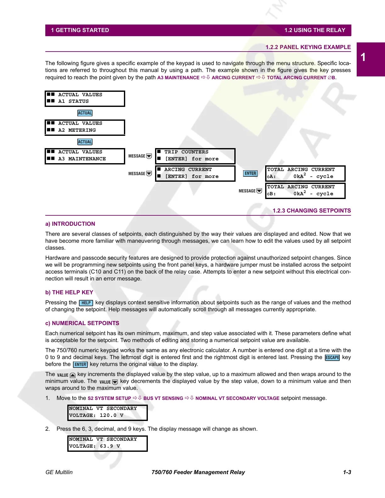
The following figure gives a specific example of the keypad is used to navigate through the menu structure. Specific loca-
tions are referred to throughout this manual by using a path. The example shown in the figure gives the key presses
required to reach the point given by the path
A3 MAINTENANCE ÖØ ARCING CURRENT ÖØ TOTAL ARCING CURRENT ∅B.
1.2.3 CHANGING SETPOINTS
a) INTRODUCTION
There are several classes of setpoints, each distinguished by the way their values are displayed and edited. Now that we
have become more familiar with maneuvering through messages, we can learn how to edit the values used by all setpoint
classes.
Hardware and passcode security features are designed to provide protection against unauthorized setpoint changes. Since
we will be programming new setpoints using the front panel keys, a hardware jumper must be installed across the setpoint
access terminals (C10 and C11) on the back of the relay case. Attempts to enter a new setpoint without this electrical con-
nection will result in an error message.
b) THE HELP KEY
Pressing the key displays context sensitive information about setpoints such as the range of values and the method
of changing the setpoint. Help messages will automatically scroll through all messages currently appropriate.
c) NUMERICAL SETPOINTS
Each numerical setpoint has its own minimum, maximum, and step value associated with it. These parameters define what
is acceptable for the setpoint. Two methods of editing and storing a numerical setpoint value are available.
The 750/760 numeric keypad works the same as any electronic calculator. A number is entered one digit at a time with the
0 to 9 and decimal keys. The leftmost digit is entered first and the rightmost digit is entered last. Pressing the key
before the key returns the original value to the display.
The key increments the displayed value by the step value, up to a maximum allowed and then wraps around to the
minimum value. The key decrements the displayed value by the step value, down to a minimum value and then
wraps around to the maximum value.
1. Move to the
S2 SYSTEM SETUP ÖØ BUS VT SENSING ÖØ NOMINAL VT SECONDARY VOLTAGE setpoint message.
2. Press the 6, 3, decimal, and 9 keys. The display message will change as shown.
ACTUAL VALUES
A1 STATUS
ACTUAL VALUES
A2 METERING
ACTUAL VALUES
A3 MAINTENANCE
TRIP COUNTERS
[ENTER] for more
ARCING CURRENT
[ENTER] for more
TOTAL ARCING CURRENT
φA: 0kA
2
- cycle
TOTAL ARCING CURRENT
φB: 0kA
2
- cycle
NOMINAL VT SECONDARY
VOLTAGE: 120.0 V
NOMINAL VT SECONDARY
VOLTAGE: 63.9 V
ACTUAL
ACTUAL
MESSAGE
MESSAGE
ENTER
MESSAGE
HELP
ESCAPE
ENTER
VALUE
VALUE
Courtesy of NationalSwitchgear.com
 Loading...


