GE Multilin 750/760 Feeder Management Relay 5-73
5 SETPOINTS 5.7 S6 MONITORING
5
5.7S6 MONITORING 5.7.1 CURRENT LEVEL
a) MAIN MENU
PATH: SETPOINTS ÖØ S6 MONITORING Ö CURRENT LEVEL
In addition to the conventional overcurrent protection elements that are used for tripping, separate phase and neutral cur-
rent level detectors are provided for alarm or control purposes. These elements allow longer time delays to be pro-
grammed.
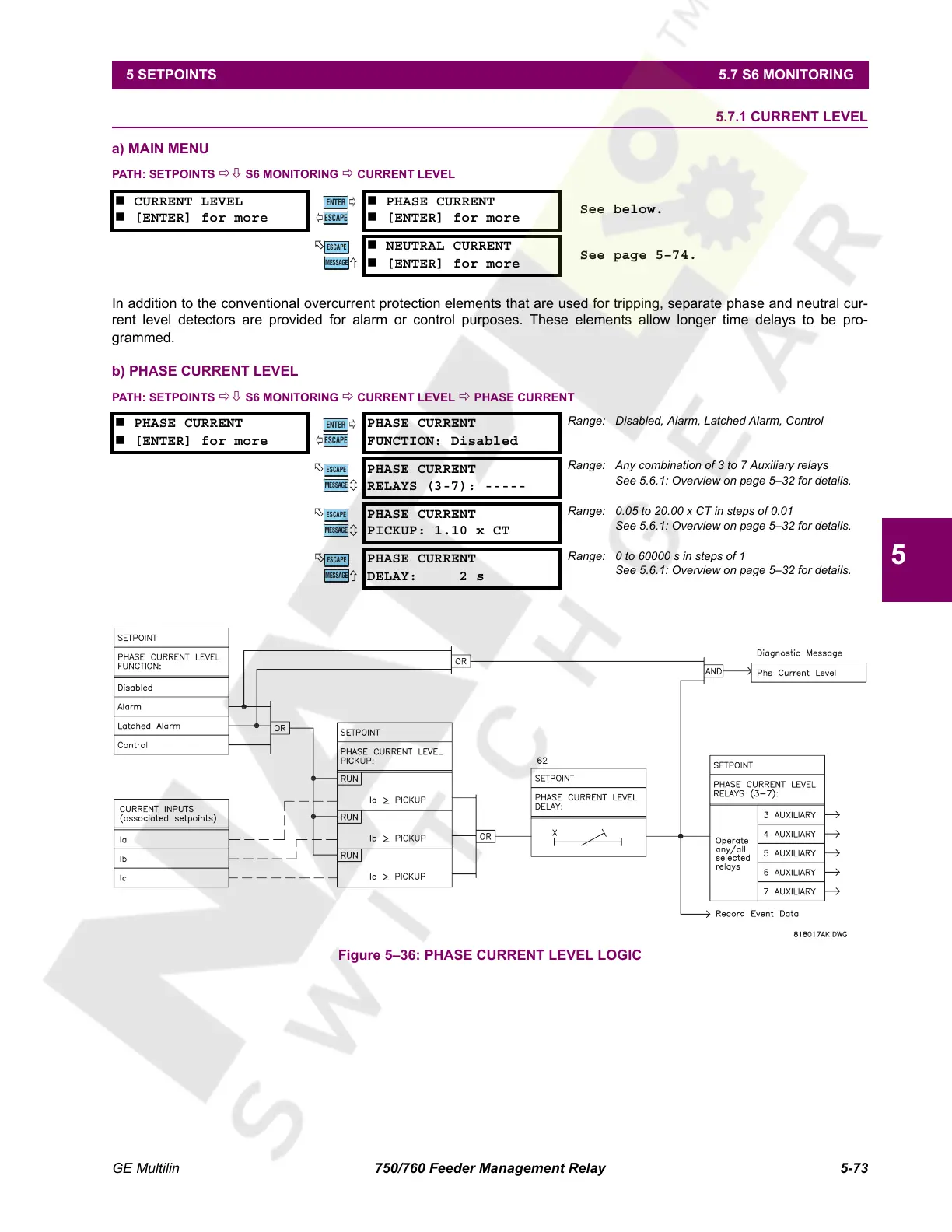
b) PHASE CURRENT LEVEL
PATH: SETPOINTS ÖØ S6 MONITORING Ö CURRENT LEVEL Ö PHASE CURRENT
Figure 5–36: PHASE CURRENT LEVEL LOGIC
CURRENT LEVEL
[ENTER] for more
PHASE CURRENT
[ENTER] for more
See below.
NEUTRAL CURRENT
[ENTER] for more
See page 5–74.
PHASE CURRENT
[ENTER] for more
PHASE CURRENT
FUNCTION: Disabled
Range: Disabled, Alarm, Latched Alarm, Control
PHASE CURRENT
RELAYS (3-7): -----
Range: Any combination of 3 to 7 Auxiliary relays
See 5.6.1: Overview on page 5–32 for details.
PHASE CURRENT
PICKUP: 1.10 x CT
Range: 0.05 to 20.00 x CT in steps of 0.01
See 5.6.1: Overview on page 5–32 for details.
PHASE CURRENT
DELAY: 2 s
Range: 0 to 60000 s in steps of 1
See 5.6.1: Overview on page 5–32 for details.
ENTER
ESCAPE
ð
ð
MESSAGE
ESCAPE
ENTER
ESCAPE
ð
ð
MESSAGE
ESCAPE
MESSAGE
ESCAPE
MESSAGE
ESCAPE
Courtesy of NationalSwitchgear.com
 Loading...


