3-14 750/760 Feeder Management Relay GE Multilin
3.2 ELECTRICAL 3 INSTALLATION
3
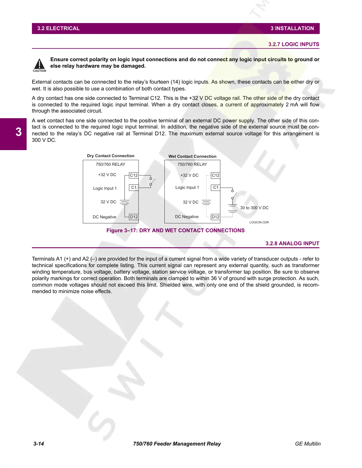
3.2.7 LOGIC INPUTS
Ensure correct polarity on logic input connections and do not connect any logic input circuits to ground or
else relay hardware may be damaged.
External contacts can be connected to the relay’s fourteen (14) logic inputs. As shown, these contacts can be either dry or
wet. It is also possible to use a combination of both contact types.
A dry contact has one side connected to Terminal C12. This is the +32 V DC voltage rail. The other side of the dry contact
is connected to the required logic input terminal. When a dry contact closes, a current of approximately 2 mA will flow
through the associated circuit.
A wet contact has one side connected to the positive terminal of an external DC power supply. The other side of this con-
tact is connected to the required logic input terminal. In addition, the negative side of the external source must be con-
nected to the relay’s DC negative rail at Terminal D12. The maximum external source voltage for this arrangement is
300 V DC.
Figure 3–17: DRY AND WET CONTACT CONNECTIONS
3.2.8 ANALOG INPUT
Terminals A1 (+) and A2 (–) are provided for the input of a current signal from a wide variety of transducer outputs - refer to
technical specifications for complete listing. This current signal can represent any external quantity, such as transformer
winding temperature, bus voltage, battery voltage, station service voltage, or transformer tap position. Be sure to observe
polarity markings for correct operation. Both terminals are clamped to within 36 V of ground with surge protection. As such,
common mode voltages should not exceed this limit. Shielded wire, with only one end of the shield grounded, is recom-
mended to minimize noise effects.
CAUTION
Dry Contact Connection
Wet Contact Connection
750/760 RELAY750/760 RELAY
C12
C1C1
C12
+32VDC
+32VDC
Logic Input 1
Logic Input 1
32VDC
32VDC
DC Negative
DC Negative D12
D12
30 to 300 V DC
LOGICIN.CD
Courtesy of NationalSwitchgear.com
 Loading...


