GE Multilin 750/760 Feeder Management Relay 3-11
3 INSTALLATION 3.2 ELECTRICAL
3
3.2.4 VOLTAGE INPUTS
The 750/760 relays have four channels for AC voltage inputs, each with an isolating transformer. Voltage transformers up to
a maximum 5000:1 ratio may be used. The nominal secondary voltage must be in the 50 to 240 V range.
The three phase inputs are designated as the “bus voltage”. The Bus VT connections most commonly used, wye and delta
(or open delta), are shown in the typical wiring diagram. Be aware that these voltage channels are internally connected as
wye. This is why the jumper between the phase B terminal and the Vcom terminal must be installed with a delta connection.
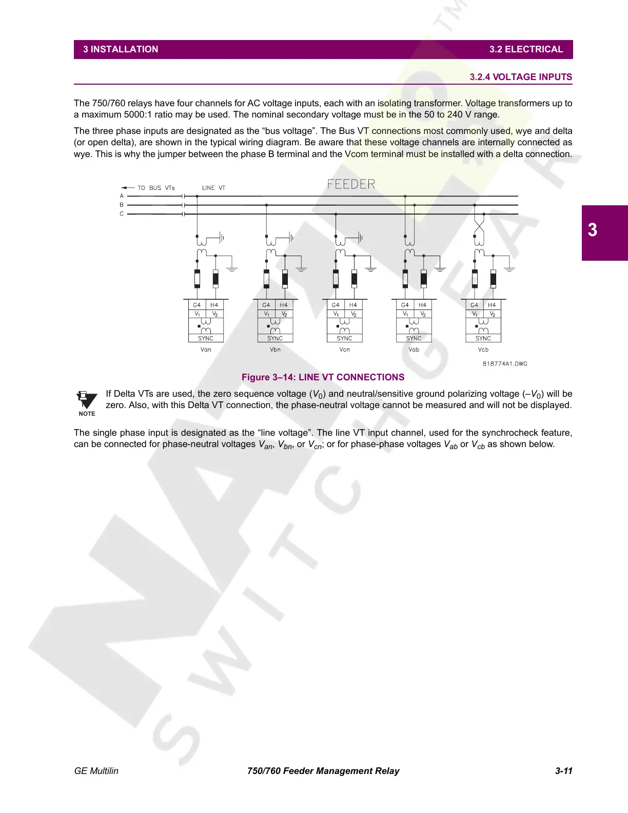
Figure 3–14: LINE VT CONNECTIONS
If Delta VTs are used, the zero sequence voltage (V
0
) and neutral/sensitive ground polarizing voltage (–V
0
) will be
zero. Also, with this Delta VT connection, the phase-neutral voltage cannot be measured and will not be displayed.
The single phase input is designated as the “line voltage”. The line VT input channel, used for the synchrocheck feature,
can be connected for phase-neutral voltages V
an
, V
bn
, or V
cn
; or for phase-phase voltages V
ab
or V
cb
as shown below.
NOTE
Courtesy of NationalSwitchgear.com
 Loading...


