3-10 750/760 Feeder Management Relay GE Multilin
3.2 ELECTRICAL 3 INSTALLATION
3
c) RESTRICTED EARTH FAULT INPUTS
Restricted Earth Fault protection is often applied to transformers having grounded wye windings to provide sensitive ground
fault detection for faults near the transformer neutral. The Sensitive Ground input (Terminals G3 and H3) can be used.
Although the 750/760 is designed for feeder protection, it can provide Restricted Earth Fault protection on trans-
formers that do not have dedicated protection. To use the 750/760 for this type of protection, a stabilizing resistor
and possibly a non-linear resistor will be required. For more details see page 5–55.
Figure 3–12: RESTRICTED EARTH FAULT INPUTS
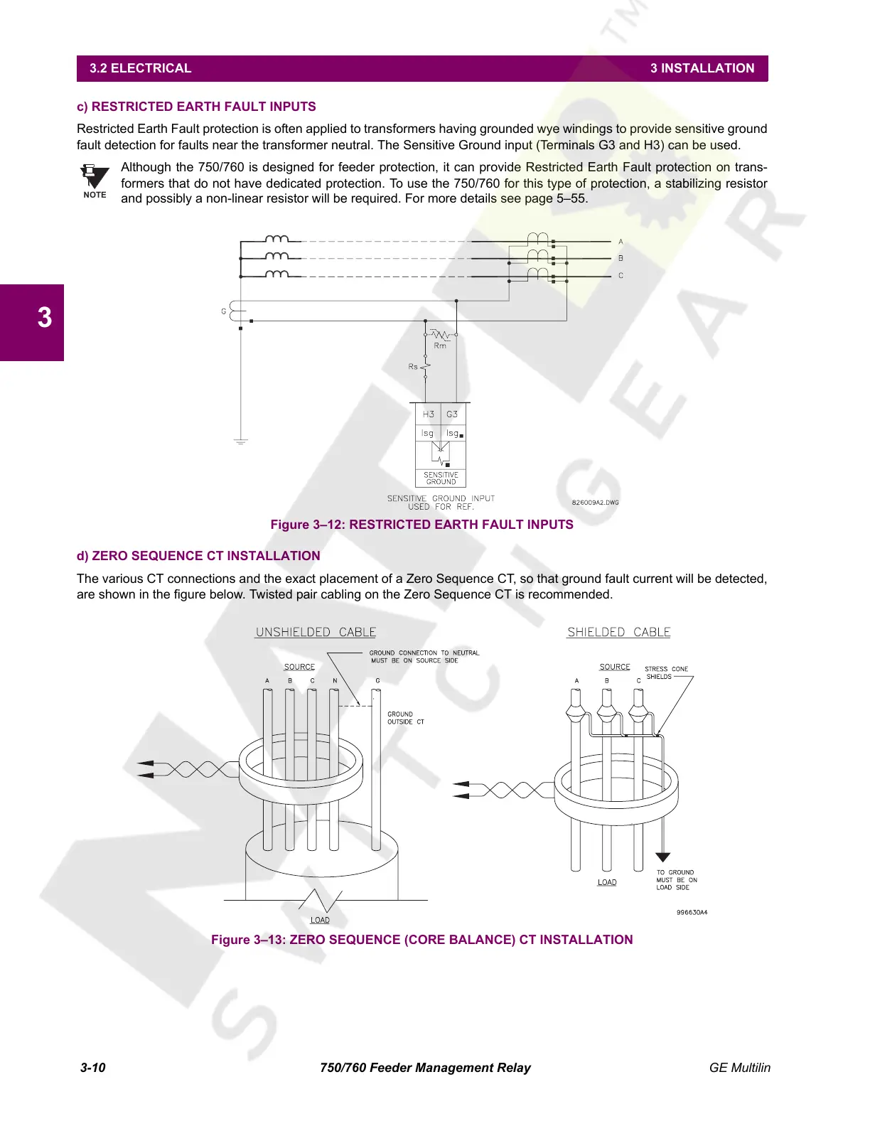
d) ZERO SEQUENCE CT INSTALLATION
The various CT connections and the exact placement of a Zero Sequence CT, so that ground fault current will be detected,
are shown in the figure below. Twisted pair cabling on the Zero Sequence CT is recommended.
Figure 3–13: ZERO SEQUENCE (CORE BALANCE) CT INSTALLATION
NOTE
Courtesy of NationalSwitchgear.com
 Loading...


