GE Multilin 750/760 Feeder Management Relay 3-15
3 INSTALLATION 3.2 ELECTRICAL
3
3.2.9 ANALOG OUTPUTS
The 750/760 relays provide eight (8) analog output channels whose full scale range was specified at the time of ordering.
Refer to Section 2.2.7: Outputs on page 2–11 the for complete listing.
Each analog output channel can be programmed to represent one of the parameters measured by the relay. For details,
see Section 5.9.3: Analog Outputs on page 5–130.
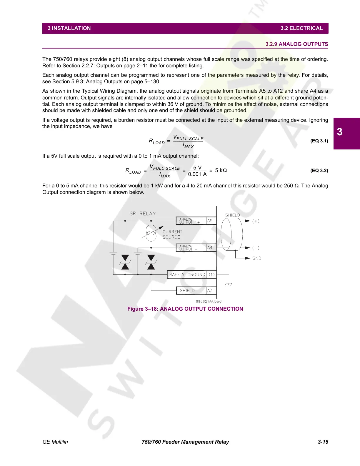
As shown in the Typical Wiring Diagram, the analog output signals originate from Terminals A5 to A12 and share A4 as a
common return. Output signals are internally isolated and allow connection to devices which sit at a different ground poten-
tial. Each analog output terminal is clamped to within 36 V of ground. To minimize the affect of noise, external connections
should be made with shielded cable and only one end of the shield should be grounded.
If a voltage output is required, a burden resistor must be connected at the input of the external measuring device. Ignoring
the input impedance, we have
(EQ 3.1)
If a 5V full scale output is required with a 0 to 1 mA output channel:
(EQ 3.2)
For a 0 to 5 mA channel this resistor would be 1 kW and for a 4 to 20 mA channel this resistor would be 250 Ω. The Analog
Output connection diagram is shown below.
Figure 3–18: ANALOG OUTPUT CONNECTION
R
LOAD
V
FULL SCALE
I
MAX
----------------------------------=
R
LOAD
V
FULL SCALE
I
MAX
----------------------------------
5 V
0.001 A
-------------------- - 5 kΩ===
Courtesy of NationalSwitchgear.com
 Loading...


