7-40 750/760 Feeder Management Relay GE Multilin
7.4 MODBUS MEMORY MAP 7 COMMUNICATIONS
7
7.4.2 DATA FORMATS
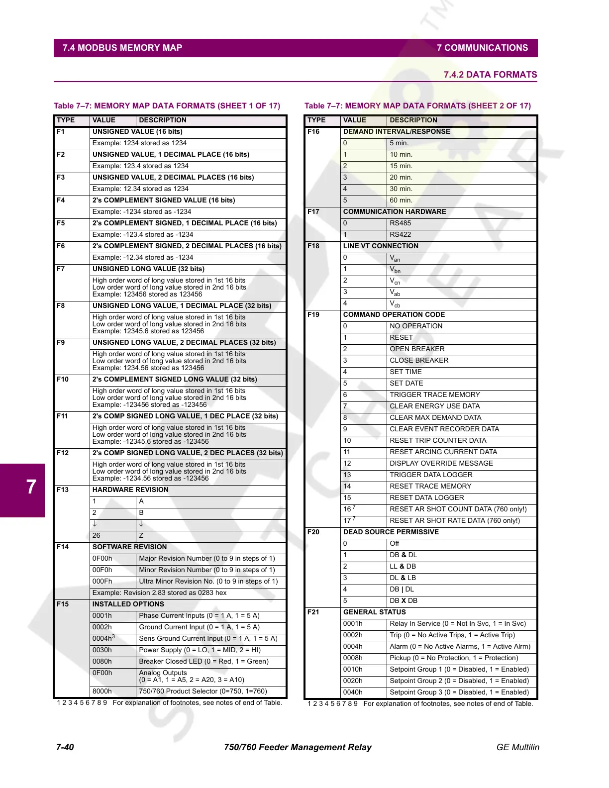
Table 7–7: MEMORY MAP DATA FORMATS (SHEET 1 OF 17)
TYPE VALUE DESCRIPTION
F1 UNSIGNED VALUE (16 bits)
Example: 1234 stored as 1234
F2 UNSIGNED VALUE, 1 DECIMAL PLACE (16 bits)
Example: 123.4 stored as 1234
F3 UNSIGNED VALUE, 2 DECIMAL PLACES (16 bits)
Example: 12.34 stored as 1234
F4 2's COMPLEMENT SIGNED VALUE (16 bits)
Example: -1234 stored as -1234
F5 2's COMPLEMENT SIGNED, 1 DECIMAL PLACE (16 bits)
Example: -123.4 stored as -1234
F6 2's COMPLEMENT SIGNED, 2 DECIMAL PLACES (16 bits)
Example: -12.34 stored as -1234
F7 UNSIGNED LONG VALUE (32 bits)
High order word of long value stored in 1st 16 bits
Low order word of long value stored in 2nd 16 bits
Example: 123456 stored as 123456
F8 UNSIGNED LONG VALUE, 1 DECIMAL PLACE (32 bits)
High order word of long value stored in 1st 16 bits
Low order word of long value stored in 2nd 16 bits
Example: 12345.6 stored as 123456
F9 UNSIGNED LONG VALUE, 2 DECIMAL PLACES (32 bits)
High order word of long value stored in 1st 16 bits
Low order word of long value stored in 2nd 16 bits
Example: 1234.56 stored as 123456
F10 2's COMPLEMENT SIGNED LONG VALUE (32 bits)
High order word of long value stored in 1st 16 bits
Low order word of long value stored in 2nd 16 bits
Example: -123456 stored as -123456
F11 2's COMP SIGNED LONG VALUE, 1 DEC PLACE (32 bits)
High order word of long value stored in 1st 16 bits
Low order word of long value stored in 2nd 16 bits
Example: -12345.6 stored as -123456
F12 2's COMP SIGNED LONG VALUE, 2 DEC PLACES (32 bits)
High order word of long value stored in 1st 16 bits
Low order word of long value stored in 2nd 16 bits
Example: -1234.56 stored as -123456
F13 HARDWARE REVISION
1A
2B
↓↓
26 Z
F14 SOFTWARE REVISION
0F00h Major Revision Number (0 to 9 in steps of 1)
00F0h Minor Revision Number (0 to 9 in steps of 1)
000Fh Ultra Minor Revision No. (0 to 9 in steps of 1)
Example: Revision 2.83 stored as 0283 hex
F15 INSTALLED OPTIONS
0001h Phase Current Inputs (0 = 1 A, 1 = 5 A)
0002h Ground Current Input (0 = 1 A, 1 = 5 A)
0004h
3
Sens Ground Current Input (0 = 1 A, 1 = 5 A)
0030h Power Supply (0 = LO, 1 = MID, 2 = HI)
0080h Breaker Closed LED (0 = Red, 1 = Green)
0F00h Analog Outputs
(0 = A1, 1 = A5, 2 = A20, 3 = A10)
8000h 750/760 Product Selector (0=750, 1=760)
1 2 3 4 5 6 7 8 9 For explanation of footnotes, see notes of end of Table.
F16 DEMAND INTERVAL/RESPONSE
05 min.
1 10 min.
2 15 min.
3 20 min.
4 30 min.
5 60 min.
F17 COMMUNICATION HARDWARE
0RS485
1RS422
F18 LINE VT CONNECTION
0V
an
1V
bn
2V
cn
3V
ab
4V
cb
F19 COMMAND OPERATION CODE
0 NO OPERATION
1 RESET
2 OPEN BREAKER
3 CLOSE BREAKER
4SET TIME
5SET DATE
6 TRIGGER TRACE MEMORY
7 CLEAR ENERGY USE DATA
8 CLEAR MAX DEMAND DATA
9 CLEAR EVENT RECORDER DATA
10 RESET TRIP COUNTER DATA
11 RESET ARCING CURRENT DATA
12 DISPLAY OVERRIDE MESSAGE
13 TRIGGER DATA LOGGER
14 RESET TRACE MEMORY
15 RESET DATA LOGGER
16
7
RESET AR SHOT COUNT DATA (760 only!)
17
7
RESET AR SHOT RATE DATA (760 only!)
F20 DEAD SOURCE PERMISSIVE
0Off
1DB & DL
2 LL & DB
3DL & LB
4DB | DL
5DB X DB
F21 GENERAL STATUS
0001h Relay In Service (0 = Not In Svc, 1 = In Svc)
0002h Trip (0 = No Active Trips, 1 = Active Trip)
0004h Alarm (0 = No Active Alarms, 1 = Active Alrm)
0008h Pickup (0 = No Protection, 1 = Protection)
0010h Setpoint Group 1 (0 = Disabled, 1 = Enabled)
0020h Setpoint Group 2 (0 = Disabled, 1 = Enabled)
0040h Setpoint Group 3 (0 = Disabled, 1 = Enabled)
Table 7–7: MEMORY MAP DATA FORMATS (SHEET 2 OF 17)
TYPE VALUE DESCRIPTION
1 2 3 4 5 6 7 8 9 For explanation of footnotes, see notes of end of Table.
Courtesy of NationalSwitchgear.com
 Loading...


