5-118 750/760 Feeder Management Relay GE Multilin
5.8 S7 CONTROL 5 SETPOINTS
5
5.8.8 AUTORECLOSE (760 ONLY)
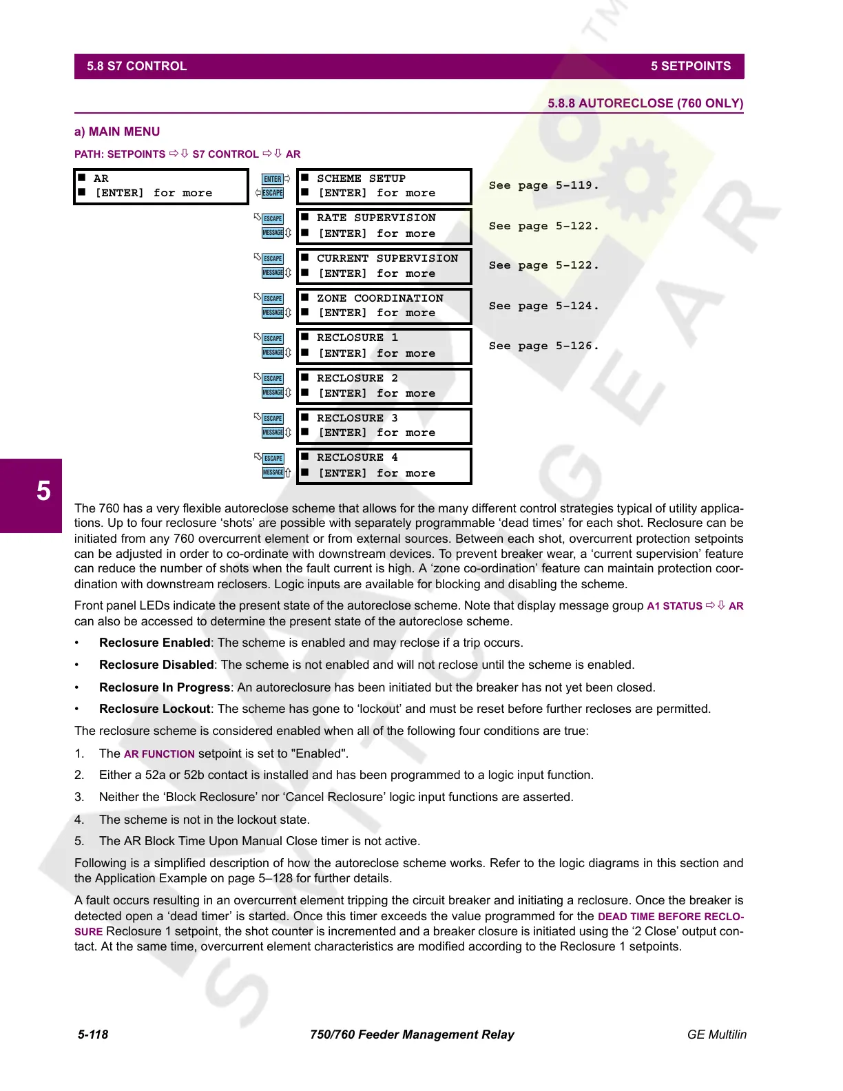
a) MAIN MENU
PATH: SETPOINTS ÖØ S7 CONTROL ÖØ AR
The 760 has a very flexible autoreclose scheme that allows for the many different control strategies typical of utility applica-
tions. Up to four reclosure ‘shots’ are possible with separately programmable ‘dead times’ for each shot. Reclosure can be
initiated from any 760 overcurrent element or from external sources. Between each shot, overcurrent protection setpoints
can be adjusted in order to co-ordinate with downstream devices. To prevent breaker wear, a ‘current supervision’ feature
can reduce the number of shots when the fault current is high. A ‘zone co-ordination’ feature can maintain protection coor-
dination with downstream reclosers. Logic inputs are available for blocking and disabling the scheme.
Front panel LEDs indicate the present state of the autoreclose scheme. Note that display message group
A1 STATUS ÖØ AR
can also be accessed to determine the present state of the autoreclose scheme.
• Reclosure Enabled: The scheme is enabled and may reclose if a trip occurs.
• Reclosure Disabled: The scheme is not enabled and will not reclose until the scheme is enabled.
• Reclosure In Progress: An autoreclosure has been initiated but the breaker has not yet been closed.
• Reclosure Lockout: The scheme has gone to ‘lockout’ and must be reset before further recloses are permitted.
The reclosure scheme is considered enabled when all of the following four conditions are true:
1. The
AR FUNCTION setpoint is set to "Enabled".
2. Either a 52a or 52b contact is installed and has been programmed to a logic input function.
3. Neither the ‘Block Reclosure’ nor ‘Cancel Reclosure’ logic input functions are asserted.
4. The scheme is not in the lockout state.
5. The AR Block Time Upon Manual Close timer is not active.
Following is a simplified description of how the autoreclose scheme works. Refer to the logic diagrams in this section and
the Application Example on page 5–128 for further details.
A fault occurs resulting in an overcurrent element tripping the circuit breaker and initiating a reclosure. Once the breaker is
detected open a ‘dead timer’ is started. Once this timer exceeds the value programmed for the
DEAD TIME BEFORE RECLO-
SURE
Reclosure 1 setpoint, the shot counter is incremented and a breaker closure is initiated using the ‘2 Close’ output con-
tact. At the same time, overcurrent element characteristics are modified according to the Reclosure 1 setpoints.
AR
[ENTER] for more
SCHEME SETUP
[ENTER] for more
See page 5–119.
RATE SUPERVISION
[ENTER] for more
See page 5–122.
CURRENT SUPERVISION
[ENTER] for more
See page 5–122.
ZONE COORDINATION
[ENTER] for more
See page 5–124.
RECLOSURE 1
[ENTER] for more
See page 5–126.
RECLOSURE 2
[ENTER] for more
RECLOSURE 3
[ENTER] for more
RECLOSURE 4
[ENTER] for more
ENTER
ESCAPE
ð
ð
MESSAGE
ESCAPE
MESSAGE
ESCAPE
MESSAGE
ESCAPE
MESSAGE
ESCAPE
MESSAGE
ESCAPE
MESSAGE
ESCAPE
MESSAGE
ESCAPE
Courtesy of NationalSwitchgear.com
 Loading...


