3-12 750/760 Feeder Management Relay GE Multilin
3.2 ELECTRICAL 3 INSTALLATION
3
3.2.5 CONTROL POWER
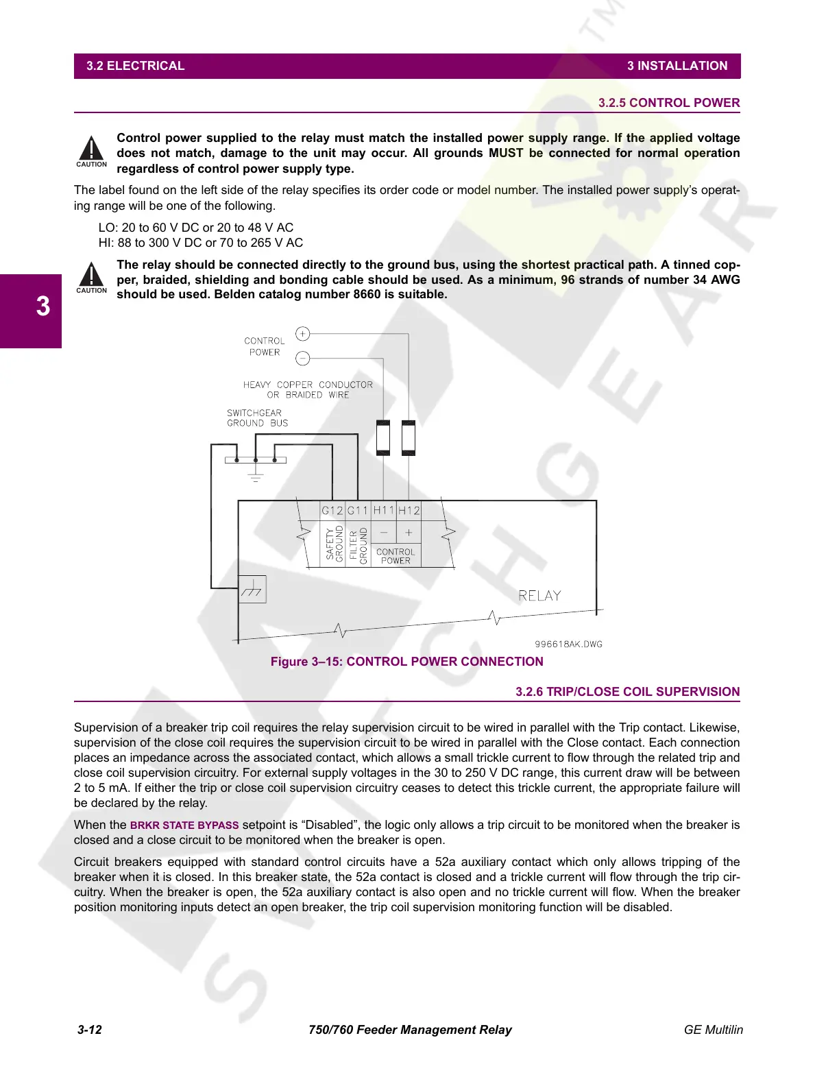
Control power supplied to the relay must match the installed power supply range. If the applied voltage
does not match, damage to the unit may occur. All grounds MUST be connected for normal operation
regardless of control power supply type.
The label found on the left side of the relay specifies its order code or model number. The installed power supply’s operat-
ing range will be one of the following.
LO: 20 to 60 V DC or 20 to 48 V AC
HI: 88 to 300 V DC or 70 to 265 V AC
The relay should be connected directly to the ground bus, using the shortest practical path. A tinned cop-
per, braided, shielding and bonding cable should be used. As a minimum, 96 strands of number 34 AWG
should be used. Belden catalog number 8660 is suitable.
Figure 3–15: CONTROL POWER CONNECTION
3.2.6 TRIP/CLOSE COIL SUPERVISION
Supervision of a breaker trip coil requires the relay supervision circuit to be wired in parallel with the Trip contact. Likewise,
supervision of the close coil requires the supervision circuit to be wired in parallel with the Close contact. Each connection
places an impedance across the associated contact, which allows a small trickle current to flow through the related trip and
close coil supervision circuitry. For external supply voltages in the 30 to 250 V DC range, this current draw will be between
2 to 5 mA. If either the trip or close coil supervision circuitry ceases to detect this trickle current, the appropriate failure will
be declared by the relay.
When the
BRKR STATE BYPASS setpoint is “Disabled”, the logic only allows a trip circuit to be monitored when the breaker is
closed and a close circuit to be monitored when the breaker is open.
Circuit breakers equipped with standard control circuits have a 52a auxiliary contact which only allows tripping of the
breaker when it is closed. In this breaker state, the 52a contact is closed and a trickle current will flow through the trip cir-
cuitry. When the breaker is open, the 52a auxiliary contact is also open and no trickle current will flow. When the breaker
position monitoring inputs detect an open breaker, the trip coil supervision monitoring function will be disabled.
CAUTION
CAUTION
Courtesy of NationalSwitchgear.com
 Loading...


