GE Multilin 750/760 Feeder Management Relay 2-5
2 INTRODUCTION 2.1 OVERVIEW
2
2.1.3 ORDERING
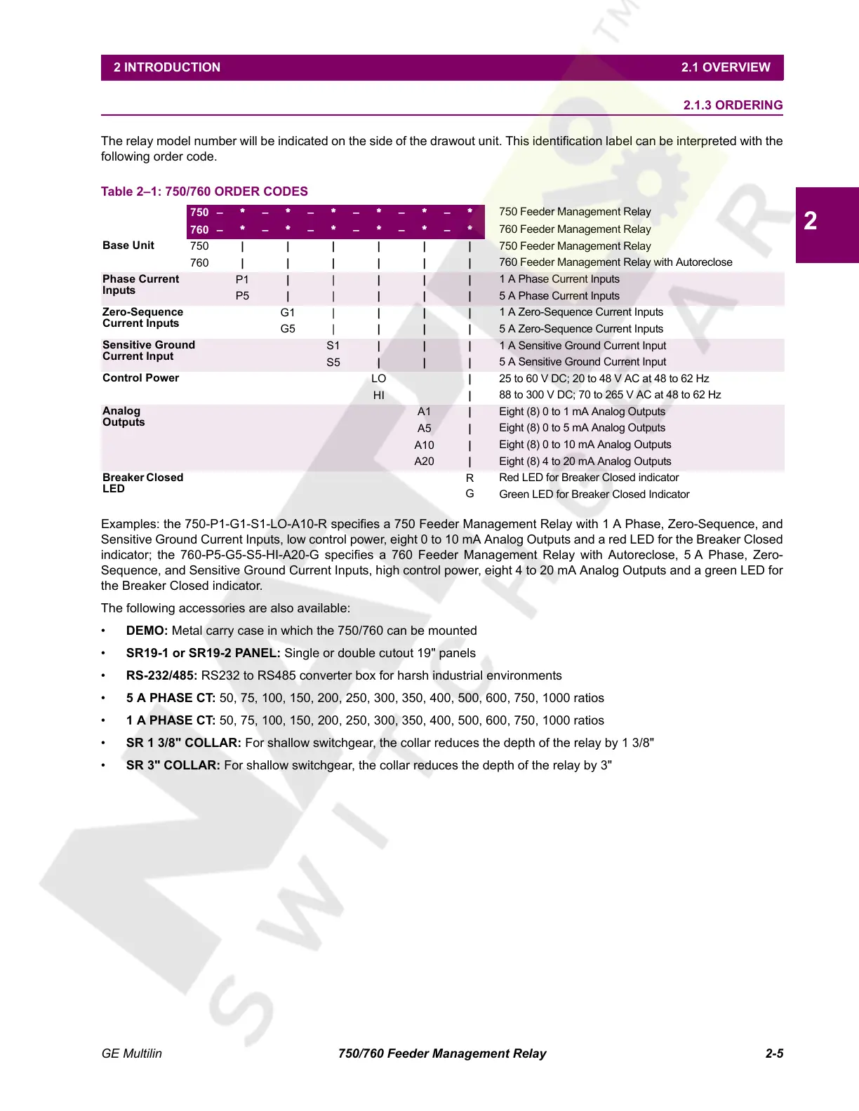
The relay model number will be indicated on the side of the drawout unit. This identification label can be interpreted with the
following order code.
Examples: the 750-P1-G1-S1-LO-A10-R specifies a 750 Feeder Management Relay with 1 A Phase, Zero-Sequence, and
Sensitive Ground Current Inputs, low control power, eight 0 to 10 mA Analog Outputs and a red LED for the Breaker Closed
indicator; the 760-P5-G5-S5-HI-A20-G specifies a 760 Feeder Management Relay with Autoreclose, 5 A Phase, Zero-
Sequence, and Sensitive Ground Current Inputs, high control power, eight 4 to 20 mA Analog Outputs and a green LED for
the Breaker Closed indicator.
The following accessories are also available:
• DEMO: Metal carry case in which the 750/760 can be mounted
• SR19-1 or SR19-2 PANEL: Single or double cutout 19" panels
• RS-232/485: RS232 to RS485 converter box for harsh industrial environments
• 5 A PHASE CT: 50, 75, 100, 150, 200, 250, 300, 350, 400, 500, 600, 750, 1000 ratios
• 1 A PHASE CT: 50, 75, 100, 150, 200, 250, 300, 350, 400, 500, 600, 750, 1000 ratios
• SR 1 3/8" COLLAR: For shallow switchgear, the collar reduces the depth of the relay by 1 3/8"
• SR 3" COLLAR: For shallow switchgear, the collar reduces the depth of the relay by 3"
Table 2–1: 750/760 ORDER CODES
750 – * – * – * – * – * – *
750 Feeder Management Relay
760 – * – * – * – * – * – *
760 Feeder Management Relay
Base Unit
750 ||||||
750 Feeder Management Relay
760 ||||||
760 Feeder Management Relay with Autoreclose
Phase Current
Inputs
P1 | | | | |
1 A Phase Current Inputs
P5 | | | | |
5 A Phase Current Inputs
Zero-Sequence
Current Inputs
G1 | |||
1 A Zero-Sequence Current Inputs
G5 | |||
5 A Zero-Sequence Current Inputs
Sensitive Ground
Current Input
S1 | | |
1 A Sensitive Ground Current Input
S5 | | |
5 A Sensitive Ground Current Input
Control Power
LO |
25 to 60 V DC; 20 to 48 V AC at 48 to 62 Hz
HI |
88 to 300 V DC; 70 to 265 V AC at 48 to 62 Hz
Analog
Outputs
A1 |
Eight (8) 0 to 1 mA Analog Outputs
A5 |
Eight (8) 0 to 5 mA Analog Outputs
A10 |
Eight (8) 0 to 10 mA Analog Outputs
A20 |
Eight (8) 4 to 20 mA Analog Outputs
Breaker Closed
LED
R
Red LED for Breaker Closed indicator
G
Green LED for Breaker Closed Indicator
Courtesy of NationalSwitchgear.com
 Loading...


