GE Multilin 750/760 Feeder Management Relay 8-33
8 COMMISSIONING TESTS 8.5 MONITORING
8
8.5MONITORING 8.5.1 CURRENT MONITORING
a) PHASE CURRENT LEVEL
To test Phase Current monitoring, use the test connections specified in Figure 8–1: Relay Test Wiring – Wye Connection or
Figure 8–2: Relay Test Wiring – Delta Connection on page 8–3. The Indications and Operations are as outlined for Phase
TOC 1 on page 8–16, except that this element has no Trip function.
1. Set the Delay time to 0.
2. Inject current at a level below the pickup level into Phase A.
3. Slowly increase the current until pickup is reached and the element generates an output.
4. Slowly reduce the current until the element resets, which should be 2% of CT less than pickup when pickup ≤ CT or 97
to 98% of pickup when pickup > CT.
5. Repeat Steps 2 to 4 for phase B and C current.
6. Set the Delay timer to the required setting.
The following procedure checks the Phase Current Level Timing:
1. Set the test source to a current at least 110% of pickup. Turn off and reset the timer.
2. Inject current into the relay and measure the time to operate.
3. Repeat Step 2 four more times and obtain an average of the time intervals
4. Disconnect the Stop Trigger.
b) NEUTRAL CURRENT LEVEL
To test Neutral Current monitoring, use the test connections specified in Figure 8–1: Relay Test Wiring – Wye Connection
or Figure 8–2: Relay Test Wiring – Delta Connection on page 8–3. The testing for this element is the same as outlined
above for Phase Current Level, except that current is the residual current injected into the phase current inputs.
8.5.2 FAULT LOCATOR
To test the Fault Locator, use the test connections specified in Figure 8–1: Relay Test Wiring – Wye Connection or Figure
8–2: Relay Test Wiring – Delta Connection on page 8–3.
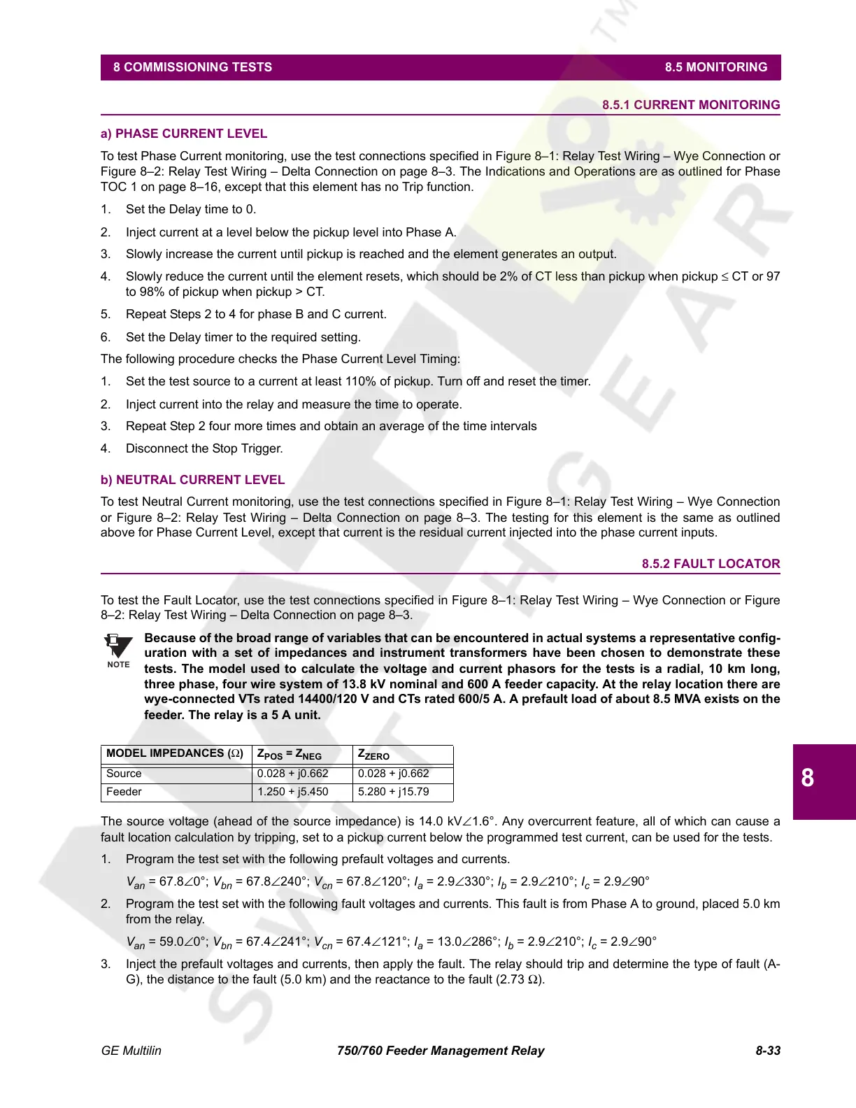
Because of the broad range of variables that can be encountered in actual systems a representative config-
uration with a set of impedances and instrument transformers have been chosen to demonstrate these
tests. The model used to calculate the voltage and current phasors for the tests is a radial, 10 km long,
three phase, four wire system of 13.8 kV nominal and 600 A feeder capacity. At the relay location there are
wye-connected VTs rated 14400/120 V and CTs rated 600/5 A. A prefault load of about 8.5 MVA exists on the
feeder. The relay is a 5 A unit.
The source voltage (ahead of the source impedance) is 14.0 kV∠1.6°. Any overcurrent feature, all of which can cause a
fault location calculation by tripping, set to a pickup current below the programmed test current, can be used for the tests.
1. Program the test set with the following prefault voltages and currents.
V
an
= 67.8∠0°; V
bn
= 67.8∠240°; V
cn
= 67.8∠120°; I
a
= 2.9∠330°; I
b
= 2.9∠210°; I
c
= 2.9∠90°
2. Program the test set with the following fault voltages and currents. This fault is from Phase A to ground, placed 5.0 km
from the relay.
V
an
= 59.0∠0°; V
bn
= 67.4∠241°; V
cn
= 67.4∠121°; I
a
= 13.0∠286°; I
b
= 2.9∠210°; I
c
= 2.9∠90°
3. Inject the prefault voltages and currents, then apply the fault. The relay should trip and determine the type of fault (A-
G), the distance to the fault (5.0 km) and the reactance to the fault (2.73 Ω).
MODEL IMPEDANCES (Ω)Z
POS
= Z
NEG
Z
ZERO
Source 0.028 + j0.662 0.028 + j0.662
Feeder 1.250 + j5.450 5.280 + j15.79
NOTE
Courtesy of NationalSwitchgear.com
 Loading...


