GE Multilin 750/760 Feeder Management Relay 5-83
5 SETPOINTS 5.7 S6 MONITORING
5
5.7.5 ANALOG INPUT
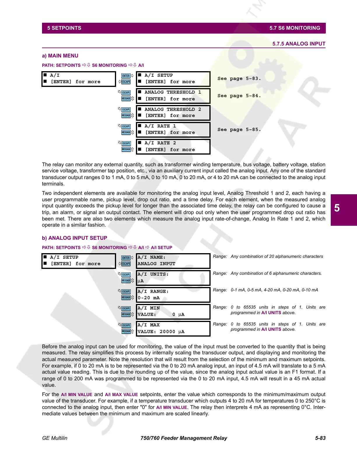
a) MAIN MENU
PATH: SETPOINTS ÖØ S6 MONITORING ÖØ A/I
The relay can monitor any external quantity, such as transformer winding temperature, bus voltage, battery voltage, station
service voltage, transformer tap position, etc., via an auxiliary current input called the analog input. Any one of the standard
transducer output ranges 0 to 1 mA, 0 to 5 mA, 0 to 10 mA, 0 to 20 mA, or 4 to 20 mA can be connected to the analog input
terminals.
Two independent elements are available for monitoring the analog input level, Analog Threshold 1 and 2, each having a
user programmable name, pickup level, drop out ratio, and a time delay. For each element, when the measured analog
input quantity exceeds the pickup level for longer than the associated time delay, the relay can be configured to cause a
trip, an alarm, or signal an output contact. The element will drop out only when the user programmed drop out ratio has
been met. There are also two elements which measure the analog input rate-of-change, Analog In Rate 1 and 2, which
operate in a similar fashion.
b) ANALOG INPUT SETUP
PATH: SETPOINTS ÖØ S6 MONITORING ÖØ A/I Ö A/I SETUP
Before the analog input can be used for monitoring, the value of the input must be converted to the quantity that is being
measured. The relay simplifies this process by internally scaling the transducer output, and displaying and monitoring the
actual measured parameter. Note the resolution that will result from the selection of the minimum and maximum setpoints.
For example, if 0 to 20 mA is to be represented via the 0 to 20 mA analog input, an input of 4.5 mA will translate to a 5 mA
actual value reading. This is due to the rounding up of the value, since the analog input actual value is an F1 format. If a
range of 0 to 200 mA was programmed to be represented via the 0 to 20 mA input, 4.5 mA will result in a 45 mA actual
value.
For the
A/I MIN VALUE and A/I MAX VALUE setpoints, enter the value which corresponds to the minimum/maximum output
value of the transducer. For example, if a temperature transducer which outputs 4 to 20 mA for temperatures 0 to 250°C is
connected to the analog input, then enter "0" for
A/I MIN VALUE. The relay then interprets 4 mA as representing 0°C. Inter-
mediate values between the minimum and maximum are scaled linearly.
A/I
[ENTER] for more
A/I SETUP
[ENTER] for more
See page 5–83.
ANALOG THRESHOLD 1
[ENTER] for more
See page 5–84.
ANALOG THRESHOLD 2
[ENTER] for more
A/I RATE 1
[ENTER] for more
See page 5–85.
A/I RATE 2
[ENTER] for more
A/I SETUP
[ENTER] for more
A/I NAME:
ANALOG INPUT
Range: Any combination of 20 alphanumeric characters
A/I UNITS:
μA
Range: Any combination of 6 alphanumeric characters.
A/I RANGE:
0-20 mA
Range: 0-1 mA, 0-5 mA, 4-20 mA, 0-20 mA, 0-10 mA
A/I MIN
VALUE: 0 μA
Range: 0 to 65535 units in steps of 1. Units are
programmed in A/I UNITS above.
A/I MAX
VALUE: 20000
μA
Range: 0 to 65535 units in steps of 1. Units are
programmed in A/I UNITS above.
ENTER
ESCAPE
ð
ð
MESSAGE
ESCAPE
MESSAGE
ESCAPE
MESSAGE
ESCAPE
MESSAGE
ESCAPE
ENTER
ESCAPE
ð
ð
MESSAGE
ESCAPE
MESSAGE
ESCAPE
MESSAGE
ESCAPE
MESSAGE
ESCAPE
Courtesy of NationalSwitchgear.com
 Loading...


