GE Multilin 750/760 Feeder Management Relay 5-85
5 SETPOINTS 5.7 S6 MONITORING
5
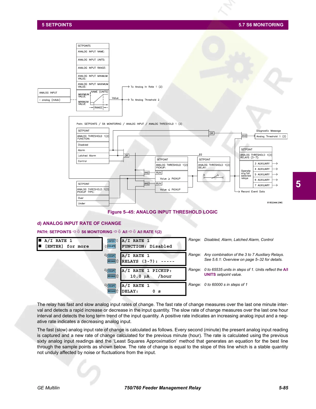
Figure 5–45: ANALOG INPUT THRESHOLD LOGIC
d) ANALOG INPUT RATE OF CHANGE
PATH: SETPOINTS ÖØ S6 MONITORING ÖØ A/I ÖØ A/I RATE 1(2)
The relay has fast and slow analog input rates of change. The fast rate of change measures over the last one minute inter-
val and detects a rapid increase or decrease in the input quantity. The slow rate of change measures over the last one hour
interval and detects the long term trend of the input quantity. A positive rate indicates an increasing analog input and a neg-
ative rate indicates a decreasing analog input.
The fast (slow) analog input rate of change is calculated as follows. Every second (minute) the present analog input reading
is captured and a new rate of change calculated for the previous minute (hour). The rate is calculated using the previous
sixty analog input readings and the ‘Least Squares Approximation’ method that generates an equation for the best line
through the sample points as shown below. The rate of change is equal to the slope of this line which is a stable quantity
not unduly affected by noise or fluctuations from the input.
A/I RATE 1
[ENTER] for more
A/I RATE 1
FUNCTION: Disabled
Range: Disabled, Alarm, Latched Alarm, Control
A/I RATE 1
RELAYS (3-7): -----
Range: Any combination of the 3 to 7 Auxiliary Relays.
See 5.6.1: Overview on page 5–32 for details.
A/I RATE 1 PICKUP:
10.0
μA /hour
Range: 0 to 65535 units in steps of 1. Units reflect the A/I
UNITS setpoint value.
A/I RATE 1
DELAY: 0 s
Range: 0 to 60000 s in steps of 1
ENTER
ESCAPE
ð
ð
MESSAGE
ESCAPE
MESSAGE
ESCAPE
MESSAGE
ESCAPE
Courtesy of NationalSwitchgear.com
 Loading...


