GE Multilin 750/760 Feeder Management Relay 5-17
5 SETPOINTS 5.3 S2 SYSTEM SETUP
5
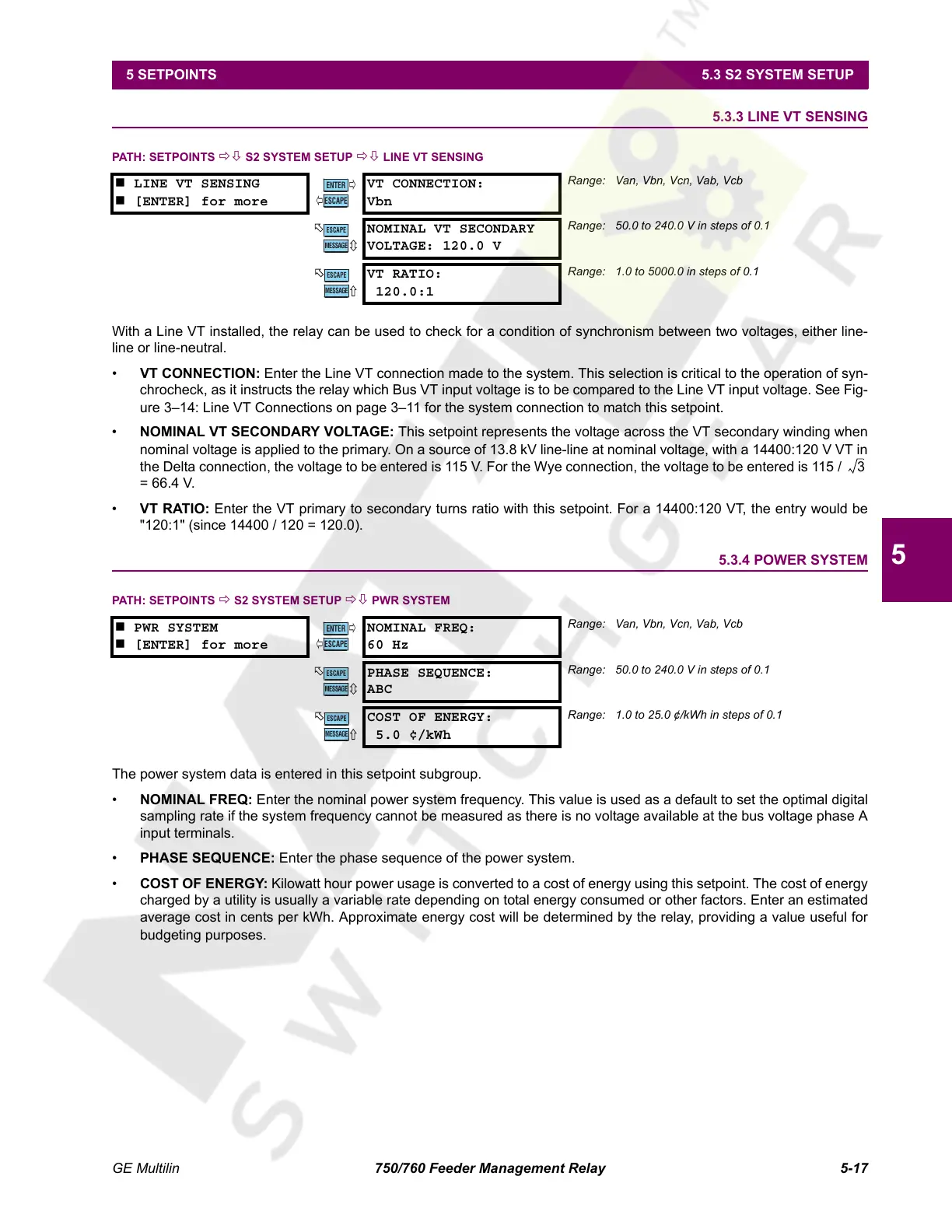
5.3.3 LINE VT SENSING
PATH: SETPOINTS ÖØ S2 SYSTEM SETUP ÖØ LINE VT SENSING
With a Line VT installed, the relay can be used to check for a condition of synchronism between two voltages, either line-
line or line-neutral.
• VT CONNECTION: Enter the Line VT connection made to the system. This selection is critical to the operation of syn-
chrocheck, as it instructs the relay which Bus VT input voltage is to be compared to the Line VT input voltage. See Fig-
ure 3–14: Line VT Connections on page 3–11 for the system connection to match this setpoint.
• NOMINAL VT SECONDARY VOLTAGE: This setpoint represents the voltage across the VT secondary winding when
nominal voltage is applied to the primary. On a source of 13.8 kV line-line at nominal voltage, with a 14400:120 V VT in
the Delta connection, the voltage to be entered is 115 V. For the Wye connection, the voltage to be entered is 115 /
= 66.4 V.
• VT RATIO: Enter the VT primary to secondary turns ratio with this setpoint. For a 14400:120 VT, the entry would be
"120:1" (since 14400 / 120 = 120.0).
5.3.4 POWER SYSTEM
PATH: SETPOINTS Ö S2 SYSTEM SETUP ÖØ PWR SYSTEM
The power system data is entered in this setpoint subgroup.
• NOMINAL FREQ: Enter the nominal power system frequency. This value is used as a default to set the optimal digital
sampling rate if the system frequency cannot be measured as there is no voltage available at the bus voltage phase A
input terminals.
• PHASE SEQUENCE: Enter the phase sequence of the power system.
• COST OF ENERGY: Kilowatt hour power usage is converted to a cost of energy using this setpoint. The cost of energy
charged by a utility is usually a variable rate depending on total energy consumed or other factors. Enter an estimated
average cost in cents per kWh. Approximate energy cost will be determined by the relay, providing a value useful for
budgeting purposes.
LINE VT SENSING
[ENTER] for more
VT CONNECTION:
Vbn
Range: Van, Vbn, Vcn, Vab, Vcb
NOMINAL VT SECONDARY
VOLTAGE: 120.0 V
Range: 50.0 to 240.0 V in steps of 0.1
VT RATIO:
120.0:1
Range: 1.0 to 5000.0 in steps of 0.1
PWR SYSTEM
[ENTER] for more
NOMINAL FREQ:
60 Hz
Range: Van, Vbn, Vcn, Vab, Vcb
PHASE SEQUENCE:
ABC
Range: 50.0 to 240.0 V in steps of 0.1
COST OF ENERGY:
5.0 ¢/kWh
Range: 1.0 to 25.0 ¢/kWh in steps of 0.1
ENTER
ESCAPE
ð
ð
MESSAGE
ESCAPE
MESSAGE
ESCAPE
3
ENTER
ESCAPE
ð
ð
MESSAGE
ESCAPE
MESSAGE
ESCAPE
Courtesy of NationalSwitchgear.com
 Loading...


