5-76 750/760 Feeder Management Relay GE Multilin
5.7 S6 MONITORING 5 SETPOINTS
5
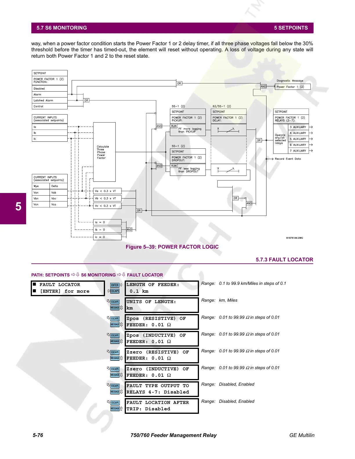
way, when a power factor condition starts the Power Factor 1 or 2 delay timer, if all three phase voltages fall below the 30%
threshold before the timer has timed-out, the element will reset without operating. A loss of voltage during any state will
return both Power Factor 1 and 2 to the reset state.
Figure 5–39: POWER FACTOR LOGIC
5.7.3 FAULT LOCATOR
PATH: SETPOINTS ÖØ S6 MONITORING ÖØ FAULT LOCATOR
FAULT LOCATOR
[ENTER] for more
LENGTH OF FEEDER:
0.1 km
Range: 0.1 to 99.9 km/Miles in steps of 0.1
UNITS OF LENGTH:
km
Range: km, Miles
Zpos (RESISTIVE) OF
FEEDER: 0.01
Ω
Range: 0.01 to 99.99
Ω
in steps of 0.01
Zpos (INDUCTIVE) OF
FEEDER: 0.01 Ω
Range: 0.01 to 99.99
Ω
in steps of 0.01
Zzero (RESISTIVE) OF
FEEDER: 0.01
Ω
Range: 0.01 to 99.99
Ω
in steps of 0.01
Zzero (INDUCTIVE) OF
FEEDER: 0.01
Ω
Range: 0.01 to 99.99
Ω
in steps of 0.01
FAULT TYPE OUTPUT TO
RELAYS 4-7: Disabled
Range: Disabled, Enabled
FAULT LOCATION AFTER
TRIP: Disabled
Range: Disabled, Enabled
ENTER
ESCAPE
ð
ð
MESSAGE
ESCAPE
MESSAGE
ESCAPE
MESSAGE
ESCAPE
MESSAGE
ESCAPE
MESSAGE
ESCAPE
MESSAGE
ESCAPE
MESSAGE
ESCAPE
Courtesy of NationalSwitchgear.com
 Loading...


