GE Multilin 750/760 Feeder Management Relay 5-107
5 SETPOINTS 5.8 S7 CONTROL
5
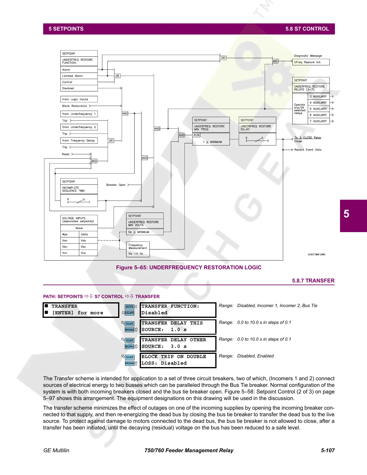
Figure 5–65: UNDERFREQUENCY RESTORATION LOGIC
5.8.7 TRANSFER
PATH: SETPOINTS ÖØ S7 CONTROL ÖØ TRANSFER
The Transfer scheme is intended for application to a set of three circuit breakers, two of which, (Incomers 1 and 2) connect
sources of electrical energy to two busses which can be paralleled through the Bus Tie breaker. Normal configuration of the
system is with both incoming breakers closed and the bus tie breaker open. Figure 5–58: Setpoint Control (2 of 3) on page
5–97 shows this arrangement. The equipment designations on this drawing will be used in the discussion.
The transfer scheme minimizes the effect of outages on one of the incoming supplies by opening the incoming breaker con-
nected to that supply, and then re-energizing the dead bus by closing the bus tie breaker to transfer the dead bus to the live
source. To protect against damage to motors connected to the dead bus, the bus tie breaker is not allowed to close, after a
transfer has been initiated, until the decaying (residual) voltage on the bus has been reduced to a safe level.
TRANSFER
[ENTER] for more
TRANSFER FUNCTION:
Disabled
Range: Disabled, Incomer 1, Incomer 2, Bus Tie
TRANSFER DELAY THIS
SOURCE: 1.0 s
Range: 0.0 to 10.0 s in steps of 0.1
TRANSFER DELAY OTHER
SOURCE: 3.0 s
Range: 0.0 to 10.0 s in steps of 0.1
BLOCK TRIP ON DOUBLE
LOSS: Disabled
Range: Disabled, Enabled
ENTER
ESCAPE
ð
ð
MESSAGE
ESCAPE
MESSAGE
ESCAPE
MESSAGE
ESCAPE
Courtesy of NationalSwitchgear.com
 Loading...


