GE Multilin 750/760 Feeder Management Relay 7-51
7 COMMUNICATIONS 7.5 DNP COMMUNICATIONS
7
7.5.2 DNP IMPLEMENTATION
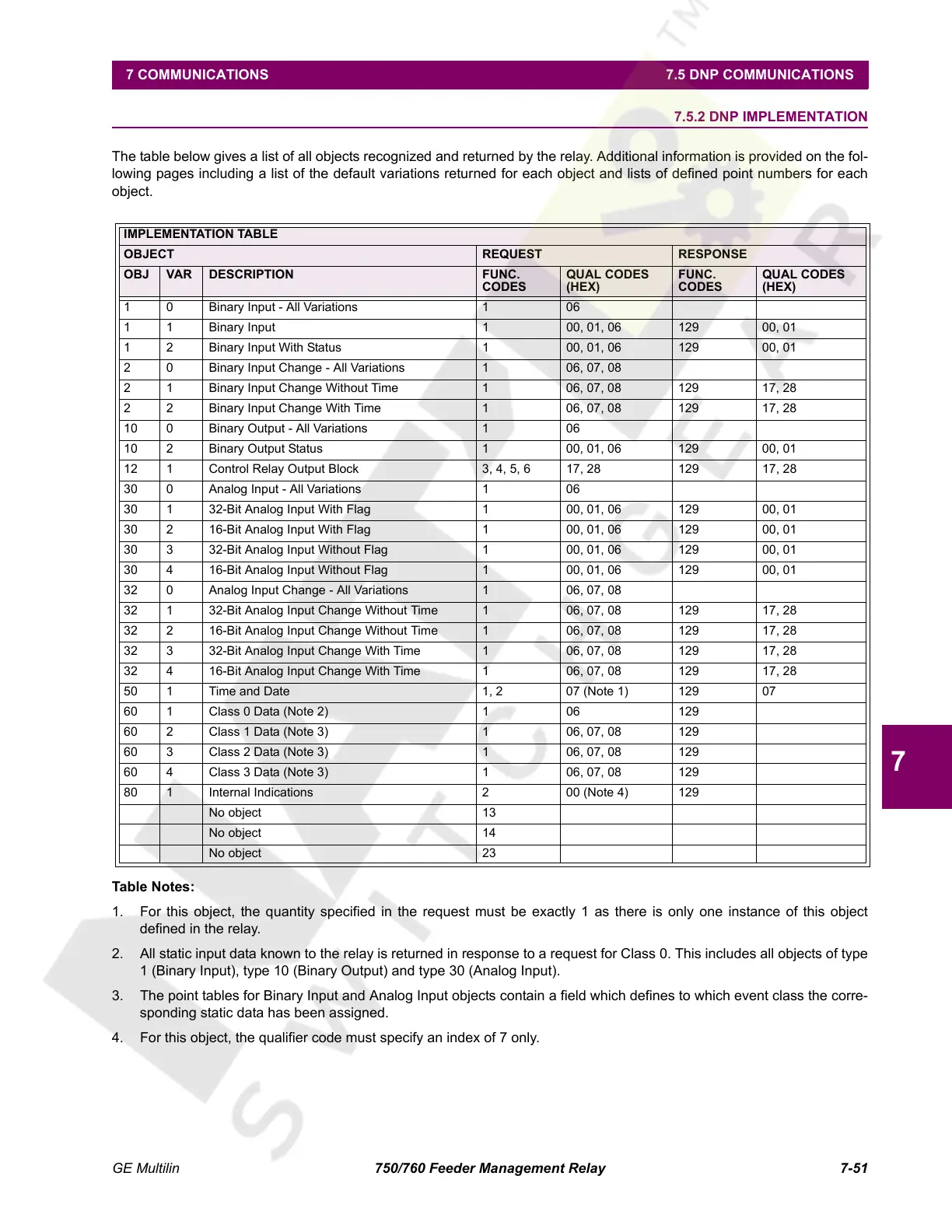
The table below gives a list of all objects recognized and returned by the relay. Additional information is provided on the fol-
lowing pages including a list of the default variations returned for each object and lists of defined point numbers for each
object.
Table Notes:
1. For this object, the quantity specified in the request must be exactly 1 as there is only one instance of this object
defined in the relay.
2. All static input data known to the relay is returned in response to a request for Class 0. This includes all objects of type
1 (Binary Input), type 10 (Binary Output) and type 30 (Analog Input).
3. The point tables for Binary Input and Analog Input objects contain a field which defines to which event class the corre-
sponding static data has been assigned.
4. For this object, the qualifier code must specify an index of 7 only.
IMPLEMENTATION TABLE
OBJECT REQUEST RESPONSE
OBJ VAR DESCRIPTION FUNC.
CODES
QUAL CODES
(HEX)
FUNC.
CODES
QUAL CODES
(HEX)
1 0 Binary Input - All Variations 1 06
1 1 Binary Input 1 00, 01, 06 129 00, 01
1 2 Binary Input With Status 1 00, 01, 06 129 00, 01
2 0 Binary Input Change - All Variations 1 06, 07, 08
2 1 Binary Input Change Without Time 1 06, 07, 08 129 17, 28
2 2 Binary Input Change With Time 1 06, 07, 08 129 17, 28
10 0 Binary Output - All Variations 1 06
10 2 Binary Output Status 1 00, 01, 06 129 00, 01
12 1 Control Relay Output Block 3, 4, 5, 6 17, 28 129 17, 28
30 0 Analog Input - All Variations 1 06
30 1 32-Bit Analog Input With Flag 1 00, 01, 06 129 00, 01
30 2 16-Bit Analog Input With Flag 1 00, 01, 06 129 00, 01
30 3 32-Bit Analog Input Without Flag 1 00, 01, 06 129 00, 01
30 4 16-Bit Analog Input Without Flag 1 00, 01, 06 129 00, 01
32 0 Analog Input Change - All Variations 1 06, 07, 08
32 1 32-Bit Analog Input Change Without Time 1 06, 07, 08 129 17, 28
32 2 16-Bit Analog Input Change Without Time 1 06, 07, 08 129 17, 28
32 3 32-Bit Analog Input Change With Time 1 06, 07, 08 129 17, 28
32 4 16-Bit Analog Input Change With Time 1 06, 07, 08 129 17, 28
50 1 Time and Date 1, 2 07 (Note 1) 129 07
60 1 Class 0 Data (Note 2) 1 06 129
60 2 Class 1 Data (Note 3) 1 06, 07, 08 129
60 3 Class 2 Data (Note 3) 1 06, 07, 08 129
60 4 Class 3 Data (Note 3) 1 06, 07, 08 129
80 1 Internal Indications 2 00 (Note 4) 129
No object 13
No object 14
No object 23
Courtesy of NationalSwitchgear.com
 Loading...


